Advertisement
Available languages
Available languages
Aufbauanleitung
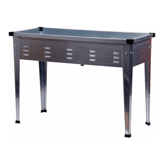
Produkt: Hochbeet 58275e
Vorbereitung
Bevor Sie das Produkt zusammenbauen, stellen Sie sicher, dass alle Teile
vorhanden sind. Vergleichen Sie die enthaltenen Teile mit der Paketinhalt-Liste
und der Verbindungselemente-Liste unten.
Wenn irgendein Teil fehlt oder beschädigt ist, versuchen Sie nicht, das Produkt
zu montieren.
Benötigte Werkzeuge für die Montage (im Lieferumfang enthalten):
Schlüssel, Inbusschlüssel
Sicherheitsinformation
Ziehen Sie alle Schrauben vor der Verwendung fest.
Dieser Pflanzkasten ist nur für den Gebrauch im Freien bestimmt. Der Boden
kann beim Gießen der Pflanzen feucht werden.
dobar e-Commerce GmbH
Fabrikstr. 3
D - 48599 Gronau
Tel.: +49 (0)25 62 / 8 1 46 27
service@dobar-e.com
1
Advertisement
Table of Contents

Related Manuals for dobar 58275e


Summary of Contents for dobar 58275e
- Page 1 GmbH Fabrikstr. 3 D - 48599 Gronau Tel.: +49 (0)25 62 / 8 1 46 27 Produkt: Hochbeet 58275e service@dobar-e.com Vorbereitung Bevor Sie das Produkt zusammenbauen, stellen Sie sicher, dass alle Teile vorhanden sind. Vergleichen Sie die enthaltenen Teile mit der Paketinhalt-Liste und der Verbindungselemente-Liste unten.
- Page 2 LIEFERUMFANG Teil Beschreibung Anzahl Teil Beschreibung Anzahl Frontblende Bodenplatte Kunststoff-Eckabdeckung Seitenblende Standbein Kunststoff-Fußkappe VERBINDUNGSELEMENTE-LISTE Inbusschlüssel M6X12 mm Schraube M6 Mutter Schraubenschlüssel Anzahl: 8 Anzahl: 8 Anzahl: 1 Anzahl: 1...
- Page 3 AUFBAUANLEITUNG Stellen Sie sicher, dass alle Standbeine (C) gut mit den Kunststoff-Fußkappen (F) befestigt sind. Stellen Sie die Blenden beim Zusammenbau auf den Kopf. Verbinden Sie die Frontblende (A) mit der Seitenblende (B) wie in Abbildung 1 gezeigt. Stellen Sie sicher, dass (B) über (A) steht, wie in Abbildung 2 gezeigt.
- Page 4 Gehen Sie bei den anderen 3 Ecken und Beinen analog vor. Benutzte Verbindungselemente: M6X12 mm Schraube M6 Mutter Den Pflanzkasten aufrecht stellen, und dann die Bodenplatte (D) in den Pflanzkasten stellen. Befestigen Sie die Kunststoff-Eckabdeckungen (E) an den vier Ecken des Pflanzkastens.
- Page 5 Germany Tel.: +49 (0)25 62 / 8 1 46 27 service@dobar-e.com product name: raised garden planter 58275e PREPARATION Before assembling product, make sure all parts are present. Compare parts with package contents list and hardware contents below. If any part is missing or damaged, do not attempt to assemble the product.
- Page 6 PACKAGE CONTENTS Part Description Quantity Part Description Quantity Front panel Bottom panel Plastic corner cover Side panel Stand leg Plastic leg cover HARDWARE CONTENTS M6X12 MM Screw M6 Nut Spanner llen key QTY. 8 QTY. 8 QTY. 1 QTY. 1...
- Page 7 ASSEMBLY INSTRUCTION (F). Make sure all stand legs are well attached to plastic leg cover Upside down the panels when assembling. Place front panel (A) and side panel (B) as picture 1 shown. Make sure (B) is on top of (A) as picture 2 shown. Attach stand leg to (B) and (A) with screw (G) and nut (H).
- Page 8 Do the same way to the other 3 corners and stand legs. Hardware Used: M6X12 MM Screw M6 Nut Turn upright the planter, place bottom panel (D) into the planter. Attach plastic corner covers (E) to 4 planter corners.
Need help?
Do you have a question about the 58275e and is the answer not in the manual?
Questions and answers