Table of Contents
Advertisement
Quick Links
INSTRUCTION MANUAL
NPPA-TT-PT
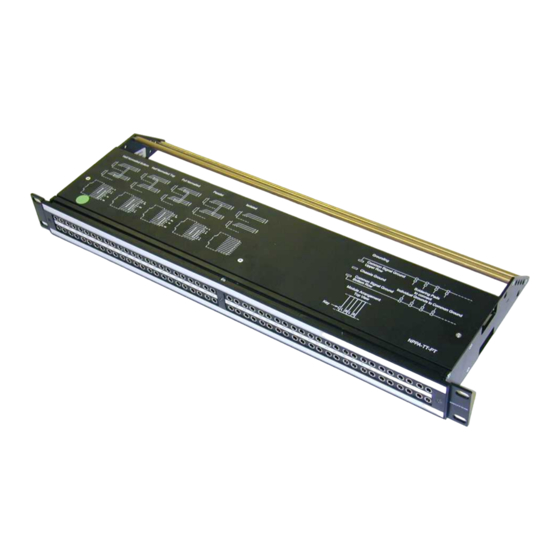
PATCH PANEL "Easy Patch"
Push Terminals
NEUTRIK AG
NEUTRIK Zürich AG
Liechtenstein
Switzerland
Tel.: +423/237 24 24 Tel.: +41 44/736 5010
Fax: +423/232 53 93 Fax: +41 44/736 5011
www.neutrik.com
Draft. Nr.:
BDA80-2/ 3102M0801
Update:
03.08.2009
Data subject to change without prior notice. ©2007 NEUTRIK . ALL RIGHTS RESERVED.
NEUTRIK (UK) Ltd.
NEUTRIK USA INC.
Great Britain
USA
Tel.: +44 1983/811 441 Tel.: +1 732/901 9488
Fax: +44 1983/811 439 Fax: +1 732/901 9608
|
96 Bantam (TT) Jacks,
NEUTRIK Tokyo Ltd.
NEUTRIK France
Japan
France
Tel.: +81 3/3663 4733
Tel.: +33 1/4131 6750 Tel.: +49 8131/28 08 90
Fax: +81 3/3663 4796
Fax: +33 1/4131 0511 Fax: +49 8131/28 08-30
NEUTRIK Vertriebs GmbH
Germany/Netherlands/Austria
Advertisement
Table of Contents

Summary of Contents for NEUTRIK NPPA-TT-PT Series
- Page 1 Fax: +44 1983/811 439 Fax: +1 732/901 9608 Fax: +81 3/3663 4796 Fax: +33 1/4131 0511 Fax: +49 8131/28 08-30 www.neutrik.com Draft. Nr.: BDA80-2/ 3102M0801 Update: 03.08.2009 Data subject to change without prior notice. ©2007 NEUTRIK . ALL RIGHTS RESERVED.
-
Page 2: Table Of Contents
NPPA-TT-PT Instruction Manual Index 1. Electrical configuration....................3 2. Replacement of Jack Pairs ..................4 3. Reconfiguration by hand....................5 4. Grounding variations ....................6 5. Wiring ..........................8 6. Cable retention to the unit....................9 7. Channel identification ....................9 8. Technical data ......................11 9. Wiring Diagram......................12 10. -
Page 3: Electrical Configuration
(2 x 48). This Patch Panel is an innovative and compact patching system (just 1 U high) for 19” rack mounting. Robustly housed in black coated steel shell and featuring precision aluminum fittings it is built to last. The Neutrik "Easy Patch” is suitable for analog and digital audio signals. -
Page 4: Replacement Of Jack Pairs
NPPA-TT-PT Instruction Manual 2. Replacement of Jack Pairs Each individual jack pair can be exchanged quickly and without fuss even while the panel is "on air". For replacement simply remove the easy accessible jack pairs. Module consisting of 2 Jack Pairs Remove Front Panel by unscrewing the 3 black cross-recessed screws (M3x8 Taptite), remove the two side-stops. -
Page 5: Reconfiguration By Hand
NPPA-TT-PT Instruction Manual The two jack pairs have to be re-assembled in the right way so that the thicker body marked “left” is put on the left side with the mark outside and readable. To complete, push the new jack pairs into the casing again with the mark on the left side (If more than one module are removed always assemble from the center to the right or left side and be careful that the keys on the left side of the jack pairs find their guiding slots. -
Page 6: Grounding Variations
NPPA-TT-PT Instruction Manual Then remove the cover with a tiny grip at the side and carefully Pull out the configuration bars you need to exchange (preferably using a small screw-driver). Insert new bars carefully by pressing them in parallel at both ends. - Page 7 NPPA-TT-PT Instruction Manual Grounding Variations (PT version) Common Signal Ground Top Row Soldering Pads Chassis Ground to connect Individual Grounds to Common Ground Common Signal Ground Bottom Row Jumper Setting for Group, Central & Chassis Common Common Signal Grounds of Top and Bottom Row separated Common Signal Ground Bottom Row connected to Chassis Ground...
-
Page 8: Wiring
NPPA-TT-PT Instruction Manual 5. Wiring For access to the terminals remove the top- and bottom-cover with three cross-recessed screws (M2.5x8) each fixed in a triangle. Rear front for wiring Spring loaded push-terminals with gas tight connection enable fast and easy wiring. NO soldering or fixing with screws is necessary. -
Page 9: Cable Retention To The Unit
NPPA-TT-PT Instruction Manual 6. Cable retention to the unit The built in cable retention bar is at the back of the casing. Simply attach the cables with cable ties to the bar as shown in the photo. For large and heavy bundles there is an additional strain relief bar NPPA-S available. It is attached to the casing with four screws. - Page 10 After marking is done assemble the parts in reversed sequence. Remove labeling strip Side Stop NOTE: For easy and perfect marking you can use our designation software “PatchLabel” which is available on our web site www.neutrik.com free of charge. Print-Out software “Patch Label” Page 10 of 13...
-
Page 11: Technical Data
NPPA-TT-PT Instruction Manual 8. Technical data 8.1 Electrical Frequency range: DC to > 50 MHz Digital suitability: Digital audio acc. to AES/EBU > 100 dB @ 10 kHz, 600 Ω terminated Channel separation: > 40 dB @ 6 MHz , 110 Ω terminated Ω... -
Page 12: Wiring Diagram
NPPA-TT-PT Instruction Manual 9. Wiring Diagram Wiring diagram Page 12 of 13... -
Page 13: Ordering Information
• Black coated steel casing with aluminum fittings • 2 x 48 highly integrated Neutrik NJ3TTA jacks with gold plated double contacts and specially designed normalling mechanism (standard: half normalled bottom row) • Integrated internal pre-wiring with selectable flexible grounding system •...
Need help?
Do you have a question about the NPPA-TT-PT Series and is the answer not in the manual?
Questions and answers