
Summary of Contents for Aquadeck AQUA-ECB-1
- Page 1 AQUA-ECB-1 Operating manual (140-2110-001 DE11) Control for swimming pool covers : for all drives of the Aquadeck series with integrated pulse generator.
-
Page 2: Table Of Contents
Content Description ............................ 3 Technical data ..........................3 Installation information ........................ 4 Functionality..........................5 Rotary button and display – functionality..................5 Programming and parameterisation ..................... 5 Drive selection ..........................5 Setting of the end positions ......................6 Fine-tuning of the positions ......................7 Operating mode .......................... -
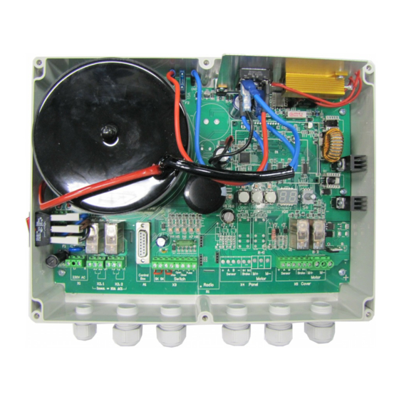
Page 3: Description
Description The control is a processor-controlled 24 VDC reversing contactor with soft-start and soft- stop function for drives of the Aqua-IPG series. The detection of the travel way is done by sensors. The end positions are programmed, the system does not require mechanical limit switches. -
Page 4: Installation Information
3. Installation information o When connecting, the relevant standards and regulations must be observed, in particular the VDE regulations, the local EVU regulations and the accident prevention regulations. o Before starting the installation work and with regard to subsequent work, switch the control to zero potential. -
Page 5: Functionality
Functionality Rotary button and display – functionality System states and inputs are displayed on to the LEDs H1 to H10. On the two-digit segment display H20 in the right part of the board, the parameters and error messages are displayed. Numerical values with more than two digits are displayed by alternating flashing of the hundreds digit and the tens digit or the ones digit. -
Page 6: Setting Of The End Positions
Setting of the end positions Setting and programming of the end positions is done via the installed buttons or the optionally available remote programming unit. Delete all storages and initiate programming mode: Press the button PROG and keep it pressed. In addition, press then the OPEN and CLOSE button simultaneously. -
Page 7: Fine-Tuning Of The Positions
Fine-tuning of the positions A position already programmed can be corrected. (Example: OPEN position) Travel the system to OPEN position. Press the PROG button and keep it pressed. Additionally, press the OPEN button briefly (approx. 1 sec.). H2 is illuminated, programming mode is initiated. -
Page 8: List Of The Menu Functions
The LEDs H1 and H3 show the status of the cover. When operating the cover, the control executes the following operation sequences: OPEN-travel from CLOSE position: CLOSE position: H3 on (Cover in CLOSE position) Command initiation OPEN command Cover moves in OPEN After the end of the travel in OPEN position, H1 is on (Cover in OPEN position) CLOSE travel from OPEN position OPEN position: H1 on (Cover in OPEN position) - Page 9 Menu no. Main menu Submenu Acceleration ramp cover 1 – 25 Sec (5 sec) Factory setting: 5 sec 1 – 25 Sec (5 sec) Deceleration ramp cover Factory setting: 5 sec Signal relay 1 function 0: Relay has no function Factory setting: 1 1: Position report OPEN 2: Position report CLOSE...
- Page 10 Menu no. Main menu Submenu Cycle counter Displays number of openings After operating the rotary button S4, 7 numbers are displayed sequentially in the right-hand segment of H20. By showing the graduation marks, it is indicated in the left-hand segment at which number you are. First graduation mark for number 1, second graduation mark for number 2 etc..
-
Page 11: Error And Information
11. Error and information In the event of a fault, the display outputs information on the present error. Any fault leads to an immediate stop (exception: Error no. 41). The following list shows the possible error messages: Error number Error message Remedial action Safety circuit is interrupted Check the connections on the terminals SK... -
Page 12: Protective Functions
Error number Error message Remedial action Runtime error Set the permissible running time (menu 33); determine the cause for a longer running time e.g. overload (reducing the speed) or defect in the power transmission Excess voltage / warning Install a chopper resistor; if necessary, check the drive type for suitability. -
Page 13: Sensor Monitoring / Emergency Mode Function
14. Sensor monitoring / emergency mode function The sensor signals are constantly evaluated and monitored for correct functioning. The LEDs H9 and H10 indicate whether the sensors operate. In proper condition, the two LEDs light up alternately (high frequenting). Note: Depending on the position of the transmitter, one of the LEDs may light up when the motor is switched off. - Page 14 Aansluitschema Buismotor / Tubemotor - Aqua ECB rood / red zwart / black grijs / grey grijs / grey bruin / browne geel / yellow groen / green blauw / bleu...
- Page 15 Aansluitschema Externemotor / Externalmotor - Aqua ECB rood / red zwart / black geel / yellow groen / green wit / white bruin / brown...
- Page 16 Aansluitschema SLEUTELSCHAKELAAR / KEYSWITCH...
Need help?
Do you have a question about the AQUA-ECB-1 and is the answer not in the manual?
Questions and answers
What is the solution for F29