Table of Contents
Advertisement
Quick Links
Advertisement
Table of Contents

Subscribe to Our Youtube Channel
Related Manuals for Benzlers Radicon G Series


Summary of Contents for Benzlers Radicon G Series
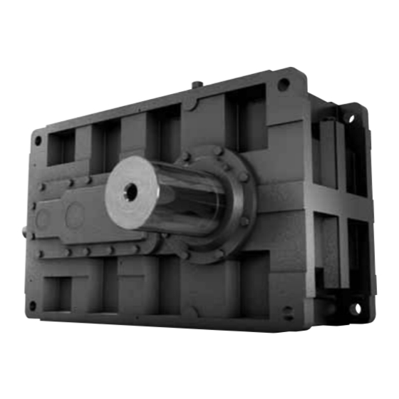
- Page 1 Series G - Industrial Reducers Installation & Maintenance IMC-1.00GB01/11...
-
Page 2: Product Safety
PRODUCT SAFETY IMPORTANT Product Safety Information General - The following information is important in ensuring safety. It must be brought to the attention of personnel involved in the selection of power transmission equipment, those responsible for the design of the machinery in which it is to be incorporated and those involved in its installation, use and maintenance. -
Page 3: Contents Page
SERIES G SERIES G CONTENTS PAGE Section Description Page No Declaration of Conformity / Incorporation General Information Weather Protection Reading the Nameplate Marking Installation 5.1 General Information 5.2 Prior to Installation 5.3 Fitting Components to Input or Output Shafts 5.4 Lifting 5.5 Installing Foot Mount Units 5.6 Installing Shaft Mount Units 5.7 Units for use in potentially explosive atmosphere... -
Page 4: Declaration Of Conformity
SERIES G INFORMATION Declaration of Conformity Products: Series G - Gear Units. Radicon Transmission Uk Ltd hereby declares that products listed above have been designed in accordance with the following Directives and Standards. products) Declaration of Incorporation According to Machinery Directive 2006/42/EC Annex IIB This product must not be put into service until the machinery into which it is to be incorporated has been declared in conformity with the provisions of the machinery directive 2006/42/EC. -
Page 5: General Information
SERIES G INFORMATION General Information The following instructions will help you achieve a satisfactory installation of your standard Series G gear unit, ensuring the best possible conditions for a long and trouble free operation. despatch, a great deal of care is taken in packing and shipping arrangements to ensure that the unit arrives at the customer in the approved condition. - Page 6 SERIES G INFORMATION Marking Units marked with this symbol are intended for use in industrial systems. Provided the units are correctly gear units only) they comply with the EU unit is supplied as a geared motor package it is important to check the nameplates of the gear unit and the motor in which the unit is to be installed.
-
Page 7: Prior To Installation
SERIES G INFORMATION Installation General WARNING! The customer shall be responsible for the proper use of articles supplied by the company, particularly the rotating shafts between their driving and driven members, and their guarding for safety, and the company shall not be responsible for any injury or damage sustained as a result of the improper use of the articles supplied. -
Page 8: Installation
SERIES G INSTALLATION Unit Size Type of Unit Input Shaft Output Shaft Parallel 2 Stage M16 x 36 mm deep 14 & 16 Parallel 3 & 4 Stage M12 x 25 mm deep M30 x 63 mm deep Right Angle 3 Stage M12 x 32 mm deep Parallel... - Page 9 SERIES G INSTALLATION Foot Mounted Units Note: Units on baseplates should if possible be mounted on the same bedplate as the prime mover. mounting positions). Note: It is important to ensure when aligning unit on baseplate that all machined mounting points are supported over their full area.
- Page 10 SERIES G INSTALLATION Torque arms are available for all shaft mounted units with parallel or right mounted to the chassis structure angle shafts. They are supplied as optional extras and are secured to gear cases as shown below. Each pair of disc springs to mounting as indicated.
- Page 11 SERIES G INSTALLATION When the shrink disc is clamped in position the high contact pressures between tapered surfaces and screw heads and their seatings ensure hermetic sealing and eliminate the possibility of fretting corrosion. Customers Shaft Shrink Disc Unit Torque Size Ød1 Ød2...
- Page 12 SERIES G INSTALLATION 5.6.2.2 Installation 5.6.2.2.1 Release locking screws gradually and in succession. Initially a quarter of a turn on each screw will avoid tilting and jamming – do not remove locking bolts completely. 5.6.2.2.3 Clean and degrease locating diameters of gear unit hollow shaft, driven shaft and 5.6.2.2.5 Grease tapered surfaces of outer ring and inner ring with Molykote 321R or similar.
- Page 13 SERIES G INSTALLATION 5.7. Units For Use In A Potentially Explosive Atmosphere prior to start up) Lubricants p27) 5.7.4. Make sure no potentially explosive atmosphere exists during installation. temperature should not exceed 40°C Check information listed on nameplates correspond to the environmental conditions of the site. 5.7.8.
- Page 14 SERIES G LUBRICATION Lubrication 6.1. General client. The grade and type of oil will be stamped on the nameplate in accordance with either of the types of oil from Tables 2 or 3 in Appendix 2. 6.2. Temperature Limitations Consult Table L1. Ambient Temperature Range (ISO) Lubricant...
-
Page 15: Motor Connections
SERIES G START UP Motor Connections To mains: regulations is essential. Motor terminal connection: RISK OF 7.2. Motor terminal connection should be made in accordance with appropriate documentation supplied by the ELECTRICAL SHOCK motor manufacturer. Starting Up 8.1. Prior To Starting Up 8.1.2. - Page 16 SERIES G MAINTENANCE 10. Maintenance 10.1. Prior To Any Maintenance Operations DANGER 10.1.1. De-energise the drive and secure against un-intentional switch on. 10.1.2. Wait until the unit has cooled down – Danger of skin burns & pressure build up. Pinch Points Watch Your Hands 10.2.
-
Page 17: Maintenance
SERIES G MAINTENANCE NOTE: Figures quoted are for oil temperatures when the unit has attained normal running temperature particularly severe it may be necessary to change the oil more frequently. When changing lubricant, Warning Do not mix Synthetic and Mineral lubricants. CAUTION 10.3.3. -
Page 18: Problem Solving
SERIES G PROBLEM SOLVING 11. Fault Diagnosis 11.1. Gear Unit Problems: Symptom Possible Causes Remedy Output shaft does not rotate, Return the gear unit / geared motor for even though the motor is Drive between shafts interrupted in the gear repair. -
Page 19: Cooling Coil
SERIES G APPENDIX 1 Cooling Coil. Cooling coil connections for water inlet and outlet pipes are Ø12mm on all sizes. Connections are therefore interchangeable. For best performance, the water supply should be at 10°C / 12°C temperature and at a Size of Unit Gear Case... - Page 20 SERIES G APPENDIX 2 Approved Lubrication. client. The grade and type of oil will be stamped on the nameplate in accordance with either of the types of oil from Tables 2 or 3. The oil change period will be stated in Section 10.3 on Page 13. WARNING CAUTION Where possible run the unit without load for a short time to circulate the lubricant thoroughly, then stop the...
- Page 21 SERIES G APPENDIX 2 Table 2 : Approved Lubricants Type E Mineral oil containing industrial EP additives. These have a high load carrying capacity. Grade Numbers notes Supplier Lubricant Range page Ambient Temperature Range °C -5 to 20 0 to 35 20 to 50 Batoyle Freedom Group Remus...
- Page 22 SERIES G APPENDIX 2 Table 3: Approved Lubricants Type H These have a medium to high load carrying capacity. Grade Numbers notes Supplier Lubricant Range page Ambient Temperature Range °C -30 to 35 20 to 50 Batoyle Freedom Group Titan Boxer Services / Millers Oils Silkgear BP Oil International Limited...
- Page 23 SERIES G APPENDIX 3 Approved Bearing Greases. Allowable Operating Temperature Range °C Supplier Lubricant Range Above BP Oil International Limited Energrease LS-EP Caltex Multifak EP Castrol International Spheerol AP Spheerol EPL Fuchs Lubricants Renolit EP Klüber Lubrication Klüberlub BE 41-542 Mobil Oil Company Limited Omega Manufacturing Division Omega 85...
-
Page 24: Shaft Alignment
SERIES G APPENDIX 4 Shaft Alignment. Figure 1 Errors of alignment fall into categories of angularity combination of both. Figure 2 Errors of angularity should be checked for, and corrected, before errors of eccentricity. Alignment in accordance with the following procedure will ensure vibration levels meeting Figure 3 those set out in ISO 10816 Part 1. - Page 25 SERIES G APPENDIX 4 Errors of Eccentricity The procedure for measuring eccentricity is precisely analogous to that used for angularity. In this case, however, the measurements are taken in a radial direction and the most convenient and accurate means of doing this utilises a dial indicator suitably clamped to one half coupling, and bearing on the hub or The permitted eccentricity error which can be accommodated in addition to that of the angularity error is as follows:- i) Input Shaft...
- Page 26 SERIES G NOTES...
- Page 27 CONTACT US AUSTRALIA DENMARK SWEDEN & NORWAY UNITED KINGDOM Radicon Transmission Benzler Transmission A/S AB Benzlers Radicon Transmission UK Ltd (Australia) PTY Ltd Fuglebævej 3D Box 922 (Landskronavägen 1) Unit J3 Australia DK-2770 Kastrup, 251 09 Helsingborg Lowfields Business Park,...
- Page 28 Benzlers Denmark +45 36 34 03 00 Finland +358 9 340 1716 Germany +49 800-350 4000 Sweden +46 42 186800 The Netherlands +31 77 324 59 00 www.benzlers.com Radicon Thailand +66 3845 9044 United Kingdom +44 (0) 1484 465 800 USA +1 847 593 9910 www.radicon.com...
Need help?
Do you have a question about the Radicon G Series and is the answer not in the manual?
Questions and answers