
Summary of Contents for American Aimers VISION II PRO
- Page 1 VISION VISION VISION VISION IMAGE PROCESSING HEADLAMP AIMER INSTRUCTION MANUAL AMERICAN AIMERS, INC 3529 WEST 6 Ave. Emporia, Kansas 66801 1-877-343-7703...
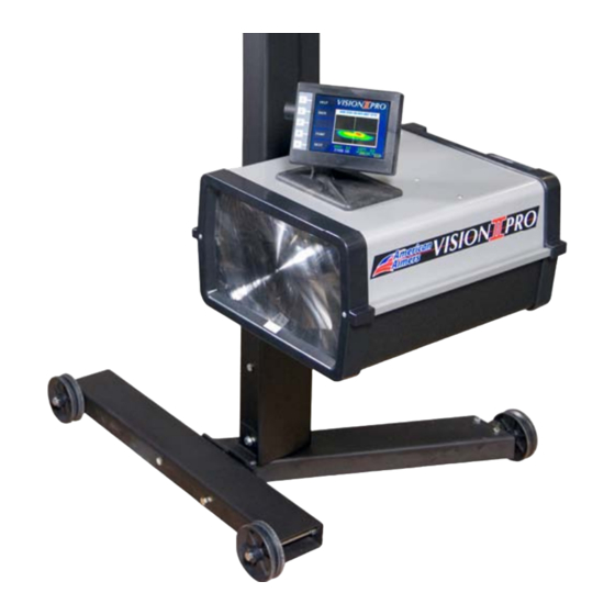
- Page 2 The Vision II Pro™ will never become obsolete. It will always be on the leading edge of technology. The system can be expanded when new aim patterns develop.
-
Page 3: Table Of Contents
Vision II Pro Manual Table of Contents Section One………………………………………….. 5 1.1 Unpacking & Inspection 4.3 Alignment Track 1.2 Assembly Procedure 4.4 Calibration 1.3 Select Language Section Five………………………………………….. 21 1.4 Alignment Method 5.1 Aim Lamps 1.5 Printer Option 5.2 Align Aimer (Vehicle Centerline) 1.6 Aimer Preparation... - Page 4 Vision II Pro Manual WARRANTY AND LIMITATION OF REMEDY Seller warrants that the items sold will be free from defects in material and workmanship for a period of one year from the date of purchase; provided, however, that Seller’s maximum liability and Buyer’s exclusive remedy, for any goods which are or become defective, shall be, at Seller’s option, the repair of the defective goods or the...
-
Page 5: Section One
3/8” - 16 Hex Nut / Qty. 2 Large Support Bag (A) Bag (A) Large Column Box 1 — Vision II Pro Head contains: (1) Vision II 3/8” - 16 Hex Nylon Loc Nut / Qty. 4 Mast Bag (B) Mast Column Bag (B) Cover 3/8”... - Page 6 Vision II Pro Optical Headlamp Aimer Assembly Procedure 1.2. STEP 1. TOOLS REQUIRED Step 3. WHEEL ASSEMBLY 3/8” Allen Wrench • Picture 3 Using 6-1/2” Hex Head Bolts, • ½” Socket Picture 1 install the wheels so that they are Jam Nut ½”...
- Page 7 Vision II Pro Optical Headlamp Aimer Assembly Procedure 1.2. Step 5. MAST ASSEMBLY Picture 5-4 1. Place Base on a sturdy flat 4. Secure Mast column in place us- Picture 5-1 Expansion surface. ing a ½” x 1” Socket Head Cap...
- Page 8 Vision II Pro Optical Headlamp Aimer Assembly Procedure 1.2. The tension on the rollers is pre- Picture 6 Picture 8 Guide Roller Groove set at the factory, however, if the unit does not roll smoothly or 6. Place the Aimer Head over...
-
Page 9: Select Language
Note: If you need to change the language simply turn the power off and repeat the process. French La mode d’emploi pour Vision II Pro est en anglais. Si vous desirez changer et choisir soit l’espagnol, soit le francais, vous pouvez le faire en suivant les instructions ci-dessous. -
Page 10: Alignment Method
There are two recommended methods to ensure the Vision II Pro aimer is aligned with the centerline of the vehicle. The LASER ALIGNMENT method utilizes the on-board laser to align the Vision II Pro unit with the vehicle centerline. The LASER ALIGNMENT method is the most widely used method and the Vision II Pro is pre-set at the factory to this mode. -
Page 11: Printer Option
Should an error be detected the monitor will display an error message. Reference the Troubleshooting Guide; if corrective action does not rectify the problem; contact an American Aimers Customer Service Representative at 1-877-343- 7703, for corrective action. If no problems are detected, the unit will display the... -
Page 12: Select Measurement
Manual The Aimer Activation Code unlocks your Vision II Aiming System. Enter the activation code provided by American Aimers. The number to be changed is indicated with a red cursor. Using the plus/minus buttons change the number to the correct value, and then push next. -
Page 13: Set-Up Aiming Bays
Vision II Pro Manual 1.9 SET-UP AIMING BAYS For aiming areas select floor surfaces that are reasonably level. Avoid extremes and variable slopes caused by floor drains. From OPTIONS screen, press BAYS button. 1.10 SET NUMBER OF BAYS This menu allows the operator to select from one to fifteen areas to be designated as aiming bays. -
Page 14: Section Two
Vision II Pro Manual SECTION TWO 2.1 SET FLOOR SLOPE Since few shop areas have the same floor slope, the floor slope of each aiming bay must be individually measured and entered. A model G2 split image transit is provided to measure floor slope. -
Page 15: Conversion Chart
Vision II Pro Manual 2.2 Conversion Chart CONVERSION CHART Degrees to Inches Degrees Inches 0.1º +/- at 25 Feet 0.523" +/- 0.2º +/- at 25 Feet 1.046" +/- 0.3º +/- at 25 Feet 1.569" +/- 0.4º +/- at 25 Feet 2.092"... - Page 16 Vision II Pro Manual 2.3 AIM OK WINDOW The AIM OK WINDOW defines the maximum allowable plus (+) or minus (-) measurement from zero of the horizontal and vertical aim axis at twenty- five (25) feet (7.6 meters). Lamps which measure within the allowable limits will register an “AIM OK”...
-
Page 17: Section Three
If condensation present, replace lamp assembly. Stabilize suspension by rocking vehicle sideways. Although the Vision II Pro Aimer can “aim” the headlamps of a vehicle with the motor idling, it is recommended that the engine be turned off during the aiming process. The vehicle headlamps must be on. -
Page 18: Section Four
The Vision II Pro™ is designed so that once the factory calibration has been performed the unit cannot become “un-calibrated” unless the unit has sustained physical damage. The calibration is checked as a part of the power-up self test. - Page 19 Vision II Pro Manual 4.4 CALLIBRATION PROCESS The Vision II Pro has been calibrated at the factory. However, it is recommended that you verify calibration before using your headlight aimer for the first time and on a monthly basis. There are...
- Page 20 Vision II Pro Manual STEP 4 Verify that the bubble in the level vial is still level. Then Verify the bezel calibration marks are perfectly aligned and the Laser dot is hitting both calibration targets, then push button (5) Save. The calibration is stored in the internal memory and the aimer is ready for use.
-
Page 21: Section Five
Vision II Pro Manual SECTION FIVE 5.1 AIM LAMPS From the main menu, press the “AIM LAMPS” button (2). 5.2 ALIGN AIMER Roll the aimer to the center of the vehicle and activate the centering laser by pressing button (3). -
Page 22: Set Bay Number
Vision II Pro Manual 5.3 SET BAY NUMBER The number displayed in the middle of the screen is the active bay. To change to a different aiming bay, press the “PLUS” button, to increase the value or the “MINUS” button to decrease the value until the desired aiming bay number is displayed. -
Page 23: Position Aimer To Lamp (Driver Side)
Vision II Pro Manual If the printer option is installed, press the (PRINT) button (4). The operator can generate a printout of the current aim information. Press the “NEXT” button (5). The aiming cycle for that lamp is complete and the aimer displays instructions to move the aimer to the driver side lamp. -
Page 24: Section Six
Vision II Pro Manual SECTION SIX 6.1 GLOSSARY LISTING Activation Code - The numeric sequence used to activate the aiming unit. Activation Screen - The screen in which the activation code is entered into the aiming unit. Aerodynamic Headlamps - The type of headlamps that are specifically designed to fit the finished design of the front of the vehicle. - Page 25 Vision II Pro Manual Computer Image Processing - The technology that allows the computer to analyze a video image which has been translated into a digital signal. Counterweight - The counterweight, located inside the vertical Mast tube, is designed to balance the aim head for smooth movement and adjustment.
- Page 26 Vision II Pro Manual Optical Center of a Lamp - The point on the face of the lamp that represents the center of the reflective parabola of that lamp. Passenger Side -The right side, or where the passenger normally seated in a vehicle built for the United States.
-
Page 27: Equipment Maintenance
The calibration is checked as part of the power-up self test to assure no problems are evident. If upon checking the calibration, the unit finds a malfunction, it will display "CALIBRATION CHECK FAILURE." If this happens, contact an American Aimers Customer Service Representative at 1-877-343-7703 for corrective action. -
Page 28: Equipment Specifications
Vision II Pro Manual 6.4 EQUIPMENT SPECIFICATIONS 6.5 REPLACEMENT PARTS Vision II Pro : Image Processing Aimer ELECTRICAL Order #82002 Freq. Input: 60 HZ Includes Floor Track & Battery Charger Power: 120 VAC Ships in Three separate boxes Printer: Optional Rechargeable Thermal Printer...
Need help?
Do you have a question about the VISION II PRO and is the answer not in the manual?
Questions and answers