Advertisement
Quick Links
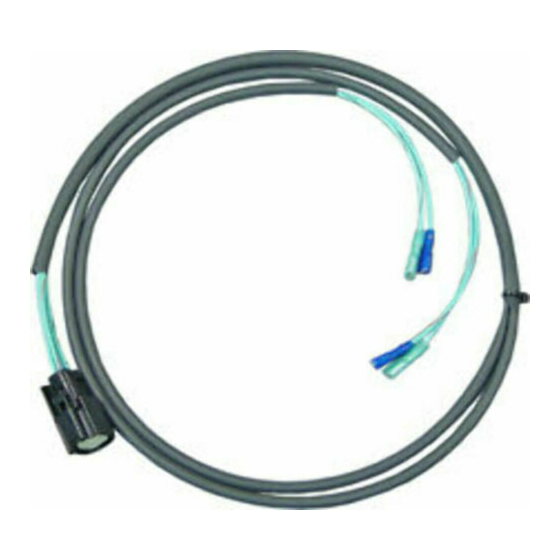
SADDLEBAG AUDIO WIRE
HARNESS KIT
P/N 2880986
APPLICATION
ALL INDIAN MOTORCYCLES WITH BOTH TRUNK AND SADDLEBAG AUDIO INSTALLED
BEFORE YOU BEGIN
Read these instructions and check to be sure all parts and tools are accounted for. Please retain
these installation instructions for future reference and parts ordering information.
2
KIT CONTENTS
Ref
1
2
3
TOOLS NEEDED
Socket Extension
Diagonal Cutters
10 mm Open End Wrench
5 mm and 6 mm Hex Key Sockets
APPROXIMATE ASSEMBLY TIME
90 min
IMPORTANT
Your Indian SADDLEBAG AUDIO WIRE HARNESS KIT is exclusively designed for your vehicle.
Please read the installation instructions thoroughly before beginning. Installation is easier if
the vehicle is clean and free of debris. For your safety, and to ensure a satisfactory installation,
perform all installation steps correctly in the sequence shown.
3
Qty
1
Vehicle Harness
1
Harness, Audio, Accy
4
Panduit
1
Instructions
Flashlight
10 mm Socket Set
4 mm Hex Key Socket (Standard)
4 mm Hex Key Socket (Ball-End Long)
P/N 9925955 Rev 02 04/15 Page 1 of 9
1
Part Description
Part Number
2412576
2412815
7080138
9925955
Ratchet
Cutters
Torque Wrench
Advertisement

Summary of Contents for Indian Motorcycle 2880986
- Page 1 SADDLEBAG AUDIO WIRE HARNESS KIT P/N 2880986 APPLICATION ALL INDIAN MOTORCYCLES WITH BOTH TRUNK AND SADDLEBAG AUDIO INSTALLED BEFORE YOU BEGIN Read these instructions and check to be sure all parts and tools are accounted for. Please retain these installation instructions for future reference and parts ordering information.
-
Page 2: Installation Instructions
INSTALLATION INSTRUCTIONS 1. On a solid, level surface, park motorcycle on side stand and turn handlebars fully to the left. 2. Raise windshield to full up position. 3. Remove the three fasteners holding the seat in place (one in the back (5 mm hex), and one on each side (6 mm hex)). - Page 3 10. Before fully removing the console, disconnect the three wire harness connectors (D) (power button, bag lock, and heated grips (if installed)). Mark the connectors with a marker before unplugging to aid in identification for re-assembly. 11. Once wires and leather are disconnected from the motorcycle, carefully set the center console assembly aside.
- Page 4 14. Disconnect the fuel pump wire harness (H). 15. Remove the two socket head screws (J) from base of fuel tank (using 6 mm hex key). 16. Remove the fuel tank by carefully lifting up the base while sliding the tank towards the rear of the vehicle.
- Page 5 Remove Outer Fairing 18. Remove chrome trim – remove two upper fasteners (L) using the 4 mm hex socket. The trim piece is now held on by a hook on the bottom and darts and grommets on the top. Pull forward on the top of the trim to disengage the darts, then lift the bezel (M) up and out of fairing.
- Page 6 22. Remove four fasteners (P) along top edge of fairing using 4 mm long-ball-end hex key socket and extension. See Figure. 23. Lift fairing away from bike and unplug wire harnesses for turn signals and foglights. 24. Set fairing aside where it will not get damaged/scratched.
- Page 7 Reinstall 34. Installation is reverse of disassembly, with torque values as shown below. a. Chrome Trim Screws (L): 36 in-lbs. (4.07 Nm). b. Headlight Bracket Screws (N): 36 in-lbs. (4.07 Nm). c. Fairing Top Edge Screws (P): 36 in-lbs. (4.07 Nm). d.
- Page 8 38. Now locate the mating plugs. a. In the front of the vehicle, between the frame and left fork and between the upper and lower triple clamps you’ll find an unused gray eight pin JST connector (U) shown in figure (this is the part of Audio Harness Kit P/N 2880302).
- Page 9 CAUTION: Ensure that the power lock and heated grip switches are plugged into the correct wire harness (see white labels on vehicle side harnesses and marks you made earlier). Ensure all wire routing is clear of moving parts. P/N 9925955 Rev 02 04/15 Page 9 of 9...
Need help?
Do you have a question about the 2880986 and is the answer not in the manual?
Questions and answers