
Subscribe to Our Youtube Channel
Related Manuals for MB QUART MBQX-STG5-1


Summary of Contents for MB QUART MBQX-STG5-1
- Page 1 Installation Manual MBQX-STG5-1 CAN-AM MAVERICK X3 STAGE 5 / 800 WATT / FIVE SPEAKER UTV-TUNED AUDIO PACKAGE...
-
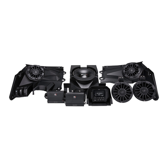
Page 2: What's Included
Thanks for choosing MB QUART! The UTV-Tuned Stage 5 Audio System for applicable Can-Am Maverick X3 vehicles (2017 and up) has been meticulously engineered for your vehicle. The process is simple and straightforward. Installation following these detailed instructions can be completed in about 3.5 hours. -
Page 3: Installation Time
INSTALLATION TIME About 3.5 hours are required to complete this installation (assuming unmodified vehicle). TOOLS AND SUPPLIES NEEDED ● Wire Strippers and Crimpers ● Phillips Screwdriver ● Flush Cut Wire Cutters (for trimming zip ties) ● Small, Straight (Jeweler’s) Screwdriver ●... -
Page 4: Vehicle Disassembly
VEHICLE DISASSEMBLY This section covers console and dash component removal. REMOVE CONSOLE SIDES Remove driver’s side console Remove passenger’s side Remove front of center console side panel using a pry tool from console side panel using a side panel on passenger’s side the top to gently release the pry tool from the top to gently (footwell area) using a pry tool... - Page 5 VEHICLE DISASSEMBLY This section covers left and right side top dash speaker panels and gauge cluster removal. REMOVE PASSENGER & DRIVER TOP DASH PANELS 10mm nut on back side Remove gas filler access door Remove three T-30 screws Remove the remaining two on passenger side.
- Page 6 VEHICLE DISASSEMBLY Removal of the center console inner cover facilitates routing wire harness from bus bar into the dash area. INNER COVER OF CENTER CONSOLE Driver’s Side View Prepare to remove forward Remove two T-30 screws Finally, remove two push pins inner cover of the center on the lower front of center on passenger’s side of cover...
- Page 7 ROUTE WIRING HARNESS This section covers connecting the main harness to the bus bar in the passenger side center console (toward the back section) and running the various breakout harness sections to their respective locations. Ground Rear Speaker Battery Harness Ignition Identify bus bar in passenger Connect the ground (black),...
- Page 8 SOURCE UNIT PREPARATION AND WIRING This section covers the preparation steps necessary to wire and pre-drill mounting for the source unit. Alternate Drill Location Remove power plug to facilitate Route source unit wiring pigtail Make four (4) crimped source source unit wiring passage and two RCA audio cables unit wiring connections by by pressing in on the top and...
-
Page 9: Amplifier Installation
AMPLIFIER INSTALLATION This section covers installation of the amplifier(s) included with the Stage 2, 3 and 5 audio system kits. An optional third amplifier and second subwoofer are covered on pages 11 & 12 of this manual. See page 17 for more details on initial amplifier settings (steps 2 and 3 below). - Page 10 MAIN SUBWOOFER INSTALLATION (SUB 1) This section covers the installation of the primary subwoofer included in Can-Am X3 Stage 3 and 5 systems. MB Quart recommends this is installed under the driver’s seat, although it can fit under either front seat. Logo...
- Page 11 OPTIONAL SUBWOOFER AMPLIFIER INSTALLATION (FOR SUB 2) This section covers the installation of the optional subwoofer amplifier included in MBQX-SUB-2, either as the second subwoofer amplifier in a Stage 3 or 5 system using new amp plate shown, or as the “add on” option for an existing Stage 2 system using the dual amp plate installed in the vehicle (requires removal).
- Page 12 Left and bolts of seat mounts*. Replace by angling the front under the right are stamped “L” and “R” with supplied MB Quart support bar for clearance of the on the bracket and enclosure. spacers for bracket tolerance.
- Page 13 REAR SPEAKER PODS INSTALLATION This section covers the wiring and installation of rear speaker pods. Note that the wiring harness is pre- wired for illumination to add illuminated speaker rings (not included with the Stage 5 kit). Connect rear speaker harness* Remove cover at the back wall Carefully route the rear to main harness in console...
- Page 14 REAR SPEAKER PODS INSTALLATION (Continued) 5mm ALLEN Driver Side Loosen the 5mm Allen screw Make two (2) crimped Use a lighter or heat gun on the swivel base to position speaker wiring connections as to heat shrink and seal the driver side pod to preferred indicated.
- Page 15 ● SOLID GRAY - Right Front Speaker (+) ● GRAY/BLACK - Right Front Speaker (-) *AFTERMARKET ROLL CAGES Clips Although MB Quart front speakers come pre-installed in the Can-Am replacement panels, they may require removal from the panel to Clips fit low-slung aftermarket roll cages Drop Panel into Place &...
- Page 16 FRONT SPEAKER INSTALLATION (Continued) This section continues front speaker installation focusing on the driver’s side. Depress Screws Tabs Replace Switches Remove switches on lower left Replace switches in the same If the vehicle has the Smart- of original driver’s side dash locations within the new MB Lok differential control module, panel by depressing the tabs...
-
Page 17: Amplifier Settings
The chart below provides general crossover filter and bass boost switch settings depending on the Can-Am X3 UTV-Tuned Audio package you have. TUNED PACKAGE TWO-CHANNEL AMPLIFIER MONO AMPLIFIER MBQX-STG5-1 HP-OFF-LP/BP Bass Boost to 0dB Switch to HP - High Pass (80Hz) LPF at 100Hz... -
Page 18: Initial Testing
INITIAL TESTING Confirm that everything is working as intended before final tuning, fitting and reassembly. STEP 1 – RECONNECT THE BATTERY First, ensure the battery is fully charged. Using a 10mm socket, then reconnect the negative terminal of the negative battery cable as indicated. STEP 2 –... -
Page 19: Fine Tuning
FINE TUNING After you have confirmed and tested that all components are working, you can fine tune the amplifier settings. Through hundreds of installations we have determined the following settings are ideal for the Can- Am X3 UTV-Tuned Audio Packages. Reference source unit volume level for these settings is 30-35 with no boost in bass, treble or EQ settings. - Page 20 As you begin reassembly, take the time to ensure no fastener, screw or clip is excluded. Review any prior disassembly steps to ensure you don’t miss any hardware during reassembly. *AFTERMARKET ROLL CAGES Although MB Quart front speakers come pre-installed in the Can-Am replacement panels, they may...
-
Page 21: Final Inspection
FINAL INSPECTION Here is a check list to make sure your vehicle is ready to hit the trails. You should pull & tighten everything so that you know your Can-Am X3 and your audio equipment are secure. ● BATTERY IS FULLY CHARGED, ESPECIALLY AFTER TESTING AND FINE TUNING ●... - Page 22 COMPLETE WIRING LAYOUT BUS BAR (CENTER CONSOLE) This is a complete wiring harness layout diagram, including optional equipment. MULTIMEDIA SOURCE UNIT OPTIONAL 2nd SUB AMP SHOWN EXTENSION HARNESS FOR 4-DOOR MODELS FRONT SPEAKER PANELS OPTIONAL SUB 2 SHOWN REAR SPEAKER PODS...
- Page 23 NOTES Use this section to record serial numbers of each product, final gain and crossover settings of amplifiers or any other wiring or installation-related details that will be helpful if you need to add on to the system or troubleshoot any unforeseen issues.
- Page 24 The Bluetooth ® word mark and logos are registered trademarks owned by the Bluetooth SIG, Inc. and any use such marks by MB Quart is under license. All product names, logos, and brands are property of their respective owners. All company, product and service names used in this literature are for identification purposes only.
Need help?
Do you have a question about the MBQX-STG5-1 and is the answer not in the manual?
Questions and answers