Table of Contents
Advertisement
Quick Links
Advertisement
Table of Contents

Related Manuals for PeakTech 1135

Summary of Contents for PeakTech 1135
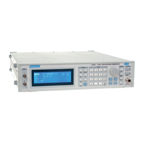
- Page 1 ® PeakTech 1135 RF Vector Signal Generator Power Supply AC Input : @115V H – N : 115V H – G : 115V N – G : < 5V Notice - Always use the three-prong AC Power cord supplied with this product.
- Page 2 ® PeakTech 1135 Read First In order for a long period of trouble-free service of the instrument, please pay special attention to the following precautions: 1. Protect the instrument from excessive impact during transportation and installation. 2. Be sure to verify whether the line voltage setting matches the line voltage used.
- Page 3 ® PeakTech 1135 Safety Symbols The following symbols on instrument and in the documentation indicate precautions which must be taken to maintain safe operation of the instrument. Warning : A warning calls attention to a procedure, practice or the like which.
- Page 4 ® PeakTech 1135 Clearing and Maintenance 1. In order for a long period of trouble-free use of the instrument, please read this manual carefully. 2. Be sure to verify whether the line voltage setting matches the line voltage used. Use a fuse with the correct rating only.
- Page 5 ® PeakTech 1135 Contents Chapter 1 GENERAL INFORMATION 1.1 Introduction ........................1 1.1.1 Carrier Frequency ...................... 1 1.1.2 Output Level ......................1 1.1.3 Digital Modulation ..................... 1 1.1.4 Up-Converter Function ....................1 1.1.5 Memory Function (Save/Recall) ................... 1 1.1.6 RS-232C ........................2 1.1.7 AUTOCAL/DIAGNOSTICS..................
-
Page 6: Table Of Contents
® PeakTech 1135 Chapter 3 OPERATINGINSTRUCTIONS 3.1 Front Panel Description...................... 6 3.2 Rear Panel Description....................... 9 3.3 Operating Examples......................11 3.3.1 Setting of the RF Output Signal .................. 11 3.3.2 Adjusting of the RF Output Signal ................12 3.3.3 Using of the Memory Register..................13 3.4 Initialize.......................... - Page 7 1135 Chapter 1 GENERAL INFORMATION 1.1 Introduction ® PeakTech 1135 is a micro-processor controlled, high frequency (10MHz~3GHz) signal generator. ® In regard of the features of PeakTech 1135, it is available to modulate external input digital signal (I/Q) and it has the function of up-conversion.
- Page 8 1.1.6 RS-232C RS-232c and a computer allows programmable control of the instrument. 1.1.7 AUTOCAL/DIAGNOSTICS ® PeakTech 1135 utilizes a unique AutoCal routine to perform a quick and easy, almost completely automatic self-calibration. 1.2 Specifications 1.2.1 Frequency -. Range : 10MHz~3GHz -.
- Page 9 ® PeakTech 1135 1.2.5 Digital Modulation -. Mode : I/Q -. External Source Input Level : 1Vpp Input impedance : 50Ω 1.2.6 UP-Converter -. Mode : IF -. External Source Input Frequency : 70MHz, 36MHz (Option : 44MHz) Input Level...
- Page 10 2.4 Installation Check ® Although every PeakTech 1135 is checked carefully before each shipment, some chance still exists for equipment damage during transportation. Therefore, the operator should verify whether the received equipment is correct or not. The following installation instruction provides the verification procedure.
- Page 11 ® PeakTech 1135 2.4.3.1 Frequency Verify that frequency commanded with keypad or rotary knob is correct. Modulation: OFF, RF Level: 0dBm 2.4.3.2 Output Level Verify that output level commanded with keypad or rotary knob is correct. Modulation = OFF, Frequency=1000MHz, RF Level = 0dBm 2.4.3.3 Digital Modulation ( I/Q )
-
Page 12: Chapter 3 Operatinginstructions
(FREQ) key 2) Press the value you want 3) Press Unit Set key (Hz, kHz, MHz) ® If the value is out of the frequency range of PeakTech 1135 (10MHz ~ 3GHz), it returns to its former value. (LEVEL) key Press this key to activate the level function so that you can change the amplitude of the RF output. - Page 13 ® PeakTech 1135 3) Press Unit Set key (uV, mV, dBm) If the value is out of the output level range of DSG-3000 (-120dBm ~ 0dBm), it returns to its former value. (IQ) key (In-Phase Quadrature-Phase) Press this key to modulate the signal with the external I/Q signal.
- Page 14 ® PeakTech 1135 11. Numeric Keypad The numeric keys are used when you input the data by number. Back Space key Press this key if you want to revise or delete the wrong number when you input the value. 13. Unit Set keys You can choose the unit of frequency and level for your convenience.
-
Page 15: Rear Panel Description
® PeakTech 1135 Level sweep : Press (SWEEP) key, . (LEVEL) key ( SWEEP ON/OFF ) key You can start of stop the function of sweep with this key. (KNOB ) key The knob increases or decreases a numeric value of cursor position. - Page 16 ® PeakTech 1135 5. Power ON/OFF switch ( 90~ 230 VAC ) ® PeakTech maintains the last setting condition before turning off. Caution Please keep the interval of two seconds at least between on and off to prevent the instrument from being damaged due to the surge current.
-
Page 17: Operating Examples
® PeakTech 1135 3.3 Operating Examples 3.3.1 Setting of the RF Output Signal In the following example, you can show the way of setting of frequency, level and modulation of RF output signal. [ The start display ] FREQ 1000.000000 MHz... -
Page 18: Adjusting Of The Rf Output Signal
® PeakTech 1135 3.3.1.4 Setting of digital modulation (ex. : IQ on, MOD on) Press these keys : ( IQ) , (MOD ON/OFF) FREQ 2000.000000 MHz MOD RF -30.0 dBm MODE EXT AC REG - - 3.3.1.5 Setting of the Up-convert function (ex. : IF on) -
Page 19: Using Of The Memory Register
MOD RF 0.0 dBm MODE EXT AC REG - - 3.3.3 Using of the Memory Register ® 3.3.3.1 Store the setting data of PeakTech 1135 to the register. 1) Press these keys : (FCN) , (MEMORY) FREQ 1000.025000 MHz MOD RF 0.0 dBm... - Page 20 ® PeakTech 1135 2) Store the above setting data to register memory 5 Press these keys : FREQ 1000.025000 MHz MOD RF 0.0 dBm MODE EXT AC REG 05 saved FREQ 1000.025000 MHz MOD RF 0.0 dBm MODE EXT AC...
-
Page 21: Initialize
MOD RF 0.0 dBm MODE EXT AC REG 05 Be careful to use this function. Because all of the memories are cleared. ® TABLE 3-2 The initial setting condition of PeakTech 1135 : OFF FREQ : 1000 MHz LEVEL : -107.0dBm... -
Page 22: Chapter 4 Gpib & Rs-232C
General Purpose Interface Bus (GPIB) is another important option in PeakTech 1135 for test automation. ® PeakTech 1135 GPIB is fully compatible with IEEE 488.2-1992 standard and the following set of commands are available. -. SH1 Source handshake -. AH1 Complete acceptor handshake capability -. -
Page 23: Installation Instructions
® The default address of PeakTech 1135 GPIB (My listen Address : MLA) set at the factory is "2", but it can easily changed from the front panel. GPIB Controller is made up of a computer with GPIB I/O interface hardware and an operating system which is compatible with IEEE-488 standard. - Page 24 ® PeakTech 1135 4.3.3.1 Parameter Commands ® Parameter commands allow the operational parameter setting of PeakTech 1135 (e.g., Frequency, Levels, etc.) Parameter command is described in Table 4-1 ~ 4-3. Parameter command format: <header> <numeric argument> <unit> <terminator> Table 4-1. Parameter Command Headers...
- Page 25 ® PeakTech 1135 Output Level dBu Output Level mV Output Level uV Output Level dBuV emf Step Level 4.3.3.2 Direct Commands Direct Command is another form of system command requiring no 200 argument. The commands are listed in Table 4-4.
- Page 26 ® PeakTech 1135 4.3.3.4 The argument for ST and RC commands is limited to a number between 0 and 99. It requires no unit. Table 4-5. RS-232C/GPIB Command List FUNCTION DATA UNIT COMMENTS 0~9, . KZ,MZ,GZ,HZ Frequency(Carrier) Frequency(Carrier) Query 0~9, .
-
Page 27: Examples
® PeakTech 1135 4.3.4 Examples 4.3.4.1 Memory Ex1) Recall stored data from REGister 10. "RC 10" Ex2) Store current front panel setting to REGister 10 "ST 10" 4.3.4.2 Programming Frequency Function Ex1) Carrier Frequency to 2500MHz "FR 2500 MZ" Ex2) Set Frequency step value to 1 MHz "FS 1 MZ"... - Page 28 ® PeakTech 1135 Ex5) Up and down level steps "LU" ; increase one level step "LD" ; decrease one level step Ex6) Set level to -13dBm, convert units to dBu, set level step value to 2dB, and decrease level by one step.
Need help?
Do you have a question about the 1135 and is the answer not in the manual?
Questions and answers