
Related Manuals for Spandau pumpen LMP Series

Summary of Contents for Spandau pumpen LMP Series
- Page 1 Original installation instruction with included Product name operating manual in accordance with EC Machinery High pressure screw pump Directive 2006/42/EC Product line: LMP… Version 03...
-
Page 2: Imprint
Directive 2006/42/EC and is an integral part of the described product. It must be kept for future use. SKF Lubrication Systems Germany GmbH Produktbereich Spandau Pumpen This original installation instruction with included Motzener Straße 35/37 operation manual was created in accordance with... -
Page 3: Table Of Contents
Table of contents page 3 Table of contents Original installation instruction in accordance with EC Machinery Directive 2006/42/EC 5.6 Sense of rotation Imprint 6. Transport, delivery and storage Service 6.1 Pump units Table of contents 6.2 Electronic and electrical devices Information concerning the EC Declaration of 6.3 General information Conformity and the EC Declaration of... -
Page 4: Information Concerning The Ec Declaration Of Conformity And The Ec Declaration Of Incorporation
Information concerning the EC Declaration of Conformity and the EC Declaration of Incorporation page 4 Information concerning the EC Declaration of Conformity and the EC Declaration of Incorporation For the product(s) designated below: ticular important for the implementation of the 67/548/EC dtd. -
Page 5: General Information
General information page 5 General information Information that is attached directly to the product Meaning of symbols and corresponding such as the examples below must be observed. information Such signs must be kept in a legible state. In this installation instruction, these symbols are used to highlight safety information that commu Rotational direction arrow •... - Page 6 page 6 Original installation instruction Product name in accordance with EC Machinery Directive 2006/42/EC For use in centralized lubrication systems Product line: LMP…...
-
Page 7: Safety Information
1. Safety information page 7 1. Safety information Especially errors that could affect safety must be Spandau High pressure screw pumps, are self Please observe the following safety instructions to resolved without delay. priming, rotating displacement pumps used to ensure trouble free functioning of the unit and pump mineral oil based oils and emulsions and prevent damage. -
Page 8: Authorized Personnel
page 8 Products of SKF Lubrication Systems Germany AG described product is installed. These persons are Working on products that have not been must not be used in conjunction with fluids, group I considered capable of such tasks due to their disconnected from the power supply can (hazardous fluids), according to the definition of education, training, and experience with valid... -
Page 9: Fluids Delivered
1 2500 mm more than 2500 mm on request 1 2500 mm Delivery temperature: 0°C to +80°C Other use or use beyond this purpose is considered unintended. Spandau Pumpen will not accept liability for damages resulting from such unintended use... -
Page 10: Assemblies And Type Designation
3. Assemblies and type designation page 10 3. Assemblies and type designation The Spandau high pressure screw pump, type LMP, is offered in 8 different sizes. The individual Table 1 Type key sizes mainly differ in dimensions and output, but not in function. -
Page 11: Design And Function
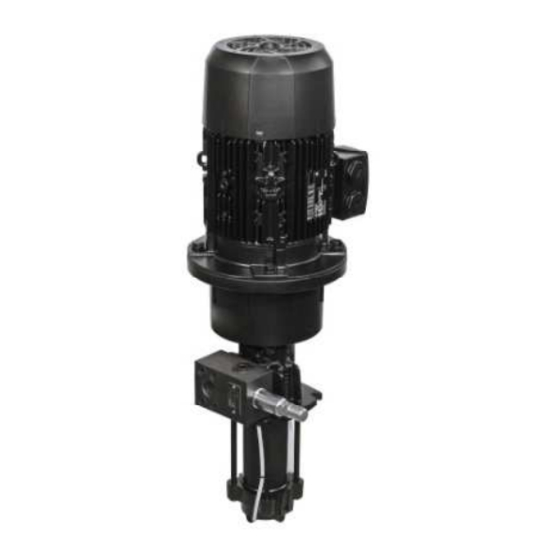
4. Design and function page 11 4. Design and function Figure 2 shows the principle design of the pump. The electrical drive (1) is installed on a pump support (3), which in turn is connected to the pressure housing (5). Drive and pump are connected by a gear coupling installed inside the pump support. -
Page 12: Installation Instruction
5. Installation instruction page 12 5. Installation instruction Regional accident prevention regulations and the the product. For information on the maximum The product described in the installation instruction operating and maintenance instructions of the permitted ambient temperature, see the technical may only be installed, operated, maintained, and operator must be observed when carrying out all data. -
Page 13: Connecting Dimensions
5. Installation instruction page 13 5.2 Connecting dimensions 5.4 Connecting of pipes The flow of the medium in the lines • Flange and connecting dimensions are dependent should not be obstructed by sharp bents, by pump version and their size. (more information The pipes are connected to the pressure housing of edge valves and return flaps. -
Page 14: Electrical Connection
5. Installation instruction page 14 5.5 Electrical connection The pump may be connected only by At a winding temperature of about 20 °C the properly qualified and instructed personnel. minimum resistance for low voltage motors is 1 k Comply with the notes in this operating per Volt rated voltage. - Page 15 Operating manual Product name High pressure screw pump Product line: LMP…...
-
Page 16: Transport, Delivery And Storage
6. Transport, delivery and storage page 16 6. Transport, delivery and storage 6.1 Pump units 6.3 General information SKF Lubrication Systems Germany GmbH products The pump must be transported only by means Ensure that no dust gets into stored products •... -
Page 17: Operation And Start Up
7. Operation and start up page 17 7. Operation and start up Check the sense of rotation of the pump upon 7.1 Filling the pump start up. It must agree with the direction indicated by the arrow on the pressure housing. Before taking it into service, all connections at the The pump must be operated only within pump must be checked. -
Page 18: Setting The Pressure Relief Valve
7. Operation and start up page 18 3. Throttle the pump to a further approx. 3 4 bar 7.2 Setting the pressure relief valve above max. pressure so that no interference occurs Pressure in the line must be monitored at the maximum permissible operating pressure. using a pressure gauge on the valve or just Screw pumps of sizes 10 to 17 are equipped with a behind the pump during the entire... -
Page 19: Shutdown
8. Shutdown page 19 . Shutdown 8.2 Definitive shutdown 8.1 Temporary shutdown All regional legal guidelines and legislation on the You temporarily shut down the described product by disconnecting the electrical, pneumatic, and/or disposal of contaminated equipment must be observed when shutting down the product for the hydraulic supply connections. -
Page 20: Maintenance
9. Maintenance page 20 9. Maintenance 9.1 General notes Also, ensure that the housing of the pump motor SKF Lubrication Systems Germany GmbH is not Working on products that have not been remains free from dust, foreign objects etc., to liable for damage caused by improper assembly, disconnected from the power supply can cause injury to persons. -
Page 21: Disassembly And Assembly Hydraulic Unit
9. Maintenance page 21 9.2 Disassembly and assembly hydraulic unit During disassembly and assembly handle all parts with greatest care. Avoid impact and shock. Clean all parts thoroughly and rework or replace them by spare parts. Unauthorized modifications to the pumps and the use of unauthorized spare parts and aids are prohibited and void the warranty. -
Page 22: Assembly Of The Hydraulic Unit
9. Maintenance page 22 9.3 Disassembly of the hydraulic unit Now slide the pump support (6) over the pump's 9.4 Assembly of the hydraulic unit First turn off the main switch. centring rim and fasten it with the bolts (10) and split washers (11), tightening it evenly. -
Page 23: Faults
10. Faults page 23 10. Faults Table 3 Error analysis and remedy Problem Possible cause Remedy You must not dismantle the product or Pump does not start Power supply defective Check the power supply. parts thereof during the statutory guar Fuse tripped Check the fuse or the motor overload switch. - Page 24 10. Faults page 24 Table 3 (contin.) Error analysis and remedy Problem Possible cause Remedy Motor overload switch cuts out Motor overload switch set too low Set the motor overload switch to the value indicated on the nameplate and ensure that immediately upon power up the pump is not overloaded.
- Page 25 10. Faults page 25 Table 3 (contin.) Error analysis and remedy Problem Possible cause Remedy Pump runs, but does not supply Air bubble in intake line or pump Vent intake line or pump. medium Wrong sense of rotation Correct sense of rotation according to the electric diagram. Noise, vibration or leaks Pump draws in air Check the filling level and correct it, if necessary.
-
Page 26: Technical Data
11. Technical data page 26 11. Technical data 11.1 Performance range 11.3 Mechanical design Delivery pressures up to p =100 bar (120 bar in oil) Component Material Delivery rate up to Q =652 l/min Spindles (screw and High performance steel drive spindles) specially hardened Screw housing... -
Page 27: Electrical Design
11. Technical data page 27 11.4 Electrical design 11.5 Dimensions The drive motors meet VDE regulations and European motor standards Abbreviation Dimensions (DIN EN 60034 1), as well as the requirements for the CE mark. 120 to 515 mm 499 to 1557 mm Designs are possible that conform to non European regulations, e.g. - Page 28 11. Technical data page 28 Bild 6: Baugrößen 10 11, 20 22, 12 13 Bild 7: Baugrößen 14 17 Bild 8: Baugrößen 27 29, 37 38...
-
Page 29: Notes
12. Notes page 29 12. Notes... - Page 30 12. Notes page 30 Order number: 951 170 018 We reserve the right to make changes! This documentation and parts thereof may only be Note that hazardous substances of any kind reprinted with the express permission of SKF and in particular the substances that are Lubrication Systems Germany GmbH.
Need help?
Do you have a question about the LMP Series and is the answer not in the manual?
Questions and answers