Table of Contents
Advertisement
Quick Links
Specifications Information and Repair Parts Manual
Please read and save this Repair Parts Manual. Read this manual and the General Operating Instructions carefully before attempting to assemble, install, operate
or maintain the product described. Protect yourself and others by observing all safety information. The Safety Instructions are contained in the General Operating
Instructions. Failure to comply with the safety instructions accompanying this product could result in personal injury and/or property damage! Retain instructions
for future reference. AMT reserves the right to discontinue any model or change specifications at any time without incurring any obligation.
©2020 AMT Pump Company, A Subsidiary of The Gorman-Rupp Company, All Rights Reserved.
Periodic maintenance and inspection is required on all pumps to insure proper operation. Unit must be clear of debris and sediment. Inspect for leaks and loose bolts. Failure to do so
voids warranty.
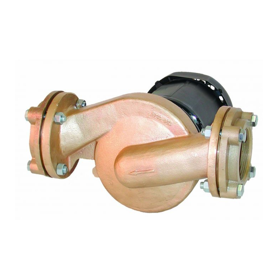
Patterson/AMT Inline Circulator Pumps
Refer to pump manual 1808-634-00 for General Operating and Safety Instructions.
DESCRIPTION
Patterson/AMT inline circulator pumps are designed for continuous duty industrial/commercial applications. Pumps are designed for liquid circulation in HVAC
and industrial/commercial systems. Pumps are available in cast iron or bronze configurations to meet your specification. Pump casing is equipped with 1.5" NPT
suction and discharge guage ports. Pumps are powered by a 56C NEMA frame electric motor with ½" conduit connection. Pump is equipped with precision lapped
mechanical shaft seal to reduce the likelihood of leakage, O-ring sealed casing and a bronze closed impeller. Liquid temperature range is 40° to 200° F (4° to 93°
C). Liquid viscosity and specific gravity must be close to water; 31 SSU and 1.00. Maximum casing pressure is 150 psi. Pump shipped with NPT flanges, flange
gaskets and flange installation hardware.
All single phase motors are equipped with automatic thermal protection. Overload protection is recommended for three phase motors, but is not supplied. Check
motor wiring before putting unit into service (see motor nameplate for specific wiring diagram). These are manual units, no controls are supplied.
All units are for use with non-flammable, non-abrasive liquids compatible
with pump component materials.
IMPORTANT: Not for use with petroleum based liquids.
SPECIFICATIONS
Suction Inlet...................................................................3" NPT Flanged
Discharge Outlet.............................................................3" NPT Flanged
Motor.................................................TEFC 1725 RPM, 56C NEMA Frame
CAST IRON UNITS (-95)
Pump construction is cast iron casing and adapter. Cast bronze impeller.
EPDM type 6 mechanical shaft seal with carbon and ceramic wear faces.
EPDM o-ring.
BRONZE UNITS (-97)
Pump construction is cast bronze casing and adapter. Cast bronze impeller.
EPDM type 6 mechanical shaft seal with carbon and ceramic wear faces.
EPDM o-ring.
UNPACKING
Refer to Repair Parts Illustration and Repair Parts List to aid in identifying
parts. Unpack and separate all pump components from shipping/packaging
materials, making sure all parts are accounted for. Retain all manuals for
reference. Package should contain: pump, flanges, circulator pump specific
manual, and general pump manual.
INSTALLATION
1.
Pump is designed for circulating liquid in a closed system for a flooded
suction application. Pump will not self-prime.
2.
Piping system must be designed for adequate thermal expansion.
3.
A pressure relief valve should be considered to protect pump casing from
5730-250-00
over pressurization and pressure spikes, especially if a check value is
installed near pump.
4.
Locate the pump so that there is sufficient room for maintenance and
servicing.
5.
There must be a sufficient supply of cooling air and ventilation around the
pump and motor to avoid excessive component temperatures.
6.
Installing a shutoff valve in both the suction and discharge piping will make
removal and servicing of the pump possible without draining the entire
system.
Figure 1 - Piping Hanger & Support
7.
Support the piping near the pump's suction and discharge with sufficient
piping hangers. This will minimize pipe strain.
NOTE: Proper motor support is required to avoid damage to pump or motor.
Use correct size motor hanger similar to the one pictured based on model
being installed. Hangers vary depending on horizontal or vertical installation
(see figure 1).
8.
Make sure bolt holes in pipe flange line up with bolt holes in pump flange.
Do not spring the suction or discharge piping into position. This will
result in excessive stain in the piping, flanges and pump casing.
1
573X Series
1/2020
Advertisement
Table of Contents

Related Manuals for GORMAN-RUPP Patterson/AMT 573 Series


Summary of Contents for GORMAN-RUPP Patterson/AMT 573 Series
- Page 1 AMT reserves the right to discontinue any model or change specifications at any time without incurring any obligation. ©2020 AMT Pump Company, A Subsidiary of The Gorman-Rupp Company, All Rights Reserved. Periodic maintenance and inspection is required on all pumps to insure proper operation. Unit must be clear of debris and sediment. Inspect for leaks and loose bolts. Failure to do so voids warranty.
- Page 2 573X Series Specifications Information and Repair Parts Manual Patterson/AMT Inline Circulator Pumps ORIENTING PUMP Water temperature in system cannot exceed 90̊ F (32̊ C) before removing The pump can be oriented in any desired position: discharge up or down, or servicing pump. If draining system, leave drain valve open during left or right.
- Page 3 573X Series Specifications Information and Repair Parts Manual Patterson/AMT Inline Circulator Pumps INSTALLATION OF NEW SEAL Set distance from motor end bell mounting face to stub shaft shoulder (at base of impeller threads) to 2.75”. Securely tighten shaft clamp fasteners locking stub shaft in position. PUMP PIPING The precision lapped faces of mechanical seal are easily damaged.
- Page 4 573X Series Specifications Information and Repair Parts Manual Patterson/AMT Inline Circulator Pump For Repair Parts contact dealer where pump was purchased. Please provide following information: -Model Number -Serial Number (if any) Part description and number as shown in parts list Figure 2 - Repair Parts Illustration 5730-250-00 1/2020...
- Page 5 573X Series Specifications Information and Repair Parts Manual Repair Parts List - Motor Part Number for Models Description 5735 5736 5730 5731 Motor 1626-M05-00 1626-021-00 1626-029-00 1626-022-00 Shaft Clamp 2105-012-00 2105-012-00 2105-012-00 2105-012-00 Drive Key 1471-030-00 1471-030-00 1471-030-00 1471-030-00 Stub Shaft 5730-140-00 5730-140-00 5730-140-00...
- Page 6 573X Series Specifications Information and Repair Parts Manual NOTES: 5730-250-00 1/2020...
- Page 7 573X Series Specifications Information and Repair Parts Manual 5730-250-00 1/2020...
- Page 8 573X Series Specifications Information and Repair Parts Manual www.amtpump.com 5730-250-00 1/2020...
Need help?
Do you have a question about the Patterson/AMT 573 Series and is the answer not in the manual?
Questions and answers