Advertisement
Quick Links
Advertisement

Related Manuals for Digitus DA-90393


Summary of Contents for Digitus DA-90393
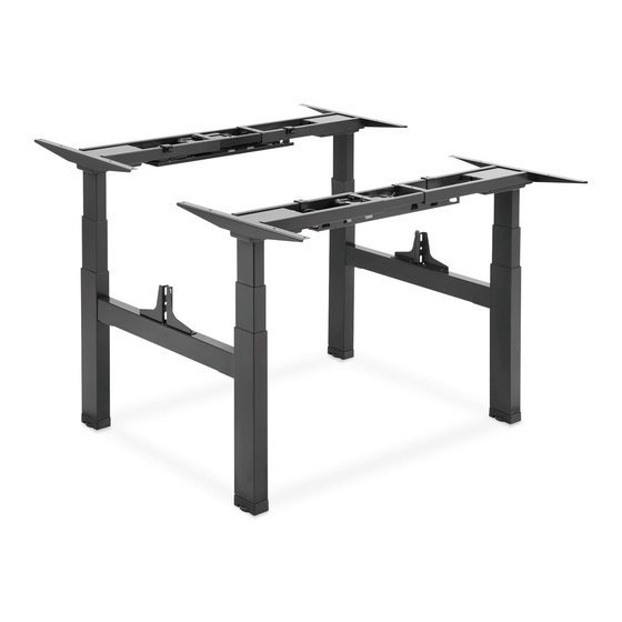
- Page 1 Electric Height-Adjustable Desk Frame, Double Workstation Manual DA-90393...
- Page 2 Preparation What are the specifications you need to know? Power Input Operation Weight Capacity Tempreature (100~240 V) 125 kg (275 lbs) x 2 (-5 °C ~ +40°C) What are the tools you require while installation? Bubble Level Allen Wrench Drill Phillips (Included) screwdriver...
-
Page 3: Package Content
Package content A (x2) B (x4) Crossbar Side Bracket C (x2) Lifting Column D (x2) E (x4) F (x2) Lifting Column Connection Kit Connection Bar G (x4) H (x2) K (x2) L (x2) I (x4) J (x2) Foot Fixing Plate Power Plug Privacy Panel Cable Management... -
Page 4: Mounting Instructions
S-I (x20) S-G (x8) S-H (x6) Anti-Vibration Pad Hex Head Cap Nut Cable Clip S-J (x1) S-K (x1) 4mm Allen Wrench 5mm Allen Wrench Mounting Instructions 1. Attaching Side Brackets Shipping blanket • Please prepare a spacious area for installation and put a shipping blanket on the area to prevent scratches on the floor and frame. - Page 5 2. Adjusting the Frame Loosen the hex head screws that fix the adjustable junction, but don’t completely take out the screws. • Ensure that the frame is placed in the center of the table. • Then adjust the frame to suit the size of the tabletop. Note: When adjusting the frame position, please make sure it doesn’t exceed the range of silk screen printing on the inner crossbar.
- Page 6 Retighten all the hex head screws to finish the adjustment. 3. Drilling Mounting Holes Use a drill to make mounting holes on the backside of the tabletop through the 8 mounting holes on • the side brackets. Note: The depth of the mounting holes should be over 10 mm and the diameter should be less than 3 mm.
- Page 7 4. Assembling the Lifting Columns Attach the lifting column to the crossbar using 8 screws S-A with Allen Wrench S-J. • Make sure the Left Leg Column C is facing inward towards the Right Leg Column D. • Repeat the same process to assemble other lifting columns. •...
- Page 8 6. Assembling the Connection Bars • Insert the assembled connection kits E into the connection bars F and attach using 8 screws S-A with Allen Wrench S-J. 7. Assembling the Feet Place the foot G on the bottom • of the lifting column and attach by pressing.
- Page 9 8. Assembling the Fixing Plate • Align the mounting holes on the fixing plate with the screw holes as shown. • Attach the fixing plate H on the center of the crossbar with 2 screws S-D using a Phillips screwdriver. •...
- Page 10 10. Attaching the Control Box • Connect the cords, control box and motors. • Repeat the same process to assemble the other control box J and controller. Connect the two motor cords to the two ports marked “M1“ and “M2“ (one on each side of the control box).
- Page 11 11. Assembling the Cable Management Tray • Align the mounting holes on the tray hangers M with the screw holes on the cable management tray. • Assemble the tray hangers to the cable management tray L with 4 screws S-E from below using a Phillips screwdriver.
- Page 12 Phillips screwdriver • Align the previously drilled screw holes with the mounting holes on the crossbar. Insert and tighten the 4 screws S-B from below. • Repeat the same process to tighten other three sides of the desktop. Drill Attach the controller to the desktop with 2 screws S-C using a •...
- Page 13 13. Level Adjustment Bubble Level There are two adjustable foot pads under each foot. If the floor isn’t even, simply turn the pad to • adjust the level to make the desk stable. Tip: Use a bubble level to check if the desktop is even.
- Page 14 Preface This electric height adjustable standing desk consists of a heavy-duty steel desk frame and a motorized height adjustment system. Please read and completely understand this manual before installation in order to make sure the safe and correct sure of the system and maintain the longevity of the overall construction and the built-in electronics.
- Page 15 Hereby Assmann Electronic GmbH declares that the Declaration of Conformity is part of the shipping content. If the Declaration of Conformity is missing, you can request it by post under the below mentioned manufacturer address. www.assmann.com Assmann Electronic GmbH Auf dem Schüffel 3 58513 Lüdenscheid Germany...