Advertisement
Table of Contents
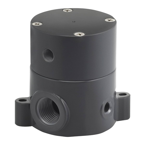
SEAL KIT REPLACEMENT INSTRUCTIONS
SERIES BSDA/M AIR-OPERATED DIAPHRAGM SHUT-OFF VALVES
1.
IMPORTANT:
Before disassembling the valve, be certain there is no pressure
acting on the inlet or outlet of the valve, including residual or head pressure.
Also, assure there is no air pressure at the air head fitting. The air head has to
be removed and could cause personal injury if the air pressure is not relieved.
2.
CAUTION: there are two springs inside the air head which could cause the air
head to fly off when the last screw is removed. Do not place your face over the
air head (item 01) when removing the screws. Hold the air head down when
removing the last screws. Remove air head (item 01) by removing the screws
(items 10, 11) and in the case of the BSDA100-TF or -PP, the nuts (item 13).
3. Remove the air head (item 01). If it appears stuck on the body, tap it on the
sides with a soft mallet until it becomes free. See caution in step 2 above.
4. Remove the piston (item 02) and the seal ring (item 03) as an assembly. If
stuck, try wiggling the assembly side to side. Prying with a screw driver can
easily damage the plastic parts so use extreme caution. Scratches in the
plastic will cause leakage.
5. Remove the U-cup (item 08) from the piston noting its orientation because the
new seal must have the same orientation. Avoid use of metal tools because a
slight scratch on the piston surface will result in air leakage past the new U-
cup seal.
6. With the piston in one hand grasp the diaphragm (item 05) with the other and
rotate counter clockwise (as viewed looking at the diaphragm), to remove it.
7. In the unlikely event that the diaphragm tears away from the screw, the screw
can be removed from the piston with a screwdriver.
8. Separate the seal ring (item 03) from the piston (item 02).
9. Remove the U-cup (item 06), noting its orientation because the new seal must
have the same orientation, and the O-ring (item 07). Again avoid the use of
metal tools (see step 5). Wipe off old lubricant which will most likely be
blackened by bits of elastomer from the seals.
10. Check all sealing surfaces for scratches. Using the appropriate lubricant (the
factory uses silicone on all BSDA valves for superior lubrication and
operation), replace the U-cups and O-ring carefully noting the orientation of
the U-cups. It is imperative that they be installed oriented as shown on the
drawing 5321, or they will not seal. Take precautions not to "roll" the O-ring
when installing it.
11. Replace the diaphragm on the piston, turning it clockwise. Screw it in as far
as it will go without using excessive force. Excessive force could cause the
diaphragm to tear away from the screw. Ideally the diaphragm should lie flat
against the piston surface. With older pistons this may not be possible. In
this case the slight "hump" at the center of the diaphragm where the screw
head lies should be flush against the piston with the outer part of the
diaphragm lying within about .005 to .010 inches from the piston surface.
12. Replace the piston/seal ring assembly into the body, with the springs. Install
the screws and tighten. It is best to tighten the head down evenly i.e. turn the
first screw down but don't fully tighten. Then turn the screw directly opposite
the first and don't fully tighten. Turn down the third screw in between the
first two and then the one opposite it. When all screws are down, finish
tightening "snugly".
At the factory, the screws are torqued as follows:
1
⁄
",
1
⁄
" BSDA: 9-12 In-lbs
4
2
3
⁄
", 1", 1
1
⁄
" BSDA: 10-13 In-lbs.
4
2
SEE NEXT PAGE FOR PARTS DRAWING
SKBSDA 0120 I 2
Advertisement
Table of Contents

Subscribe to Our Youtube Channel
Related Manuals for Plast-O-Matic BSDA Series


Summary of Contents for Plast-O-Matic BSDA Series
- Page 1 SEAL KIT REPLACEMENT INSTRUCTIONS SERIES BSDA/M AIR-OPERATED DIAPHRAGM SHUT-OFF VALVES IMPORTANT: Before disassembling the valve, be certain there is no pressure 9. Remove the U-cup (item 06), noting its orientation because the new seal must acting on the inlet or outlet of the valve, including residual or head pressure. have the same orientation, and the O-ring (item 07).
- Page 2 Description Material AIR HEAD PLASTIC PISTON PLASTIC SEAL RING PLASTIC BODY PLASTIC DIAPHRAGM TFE/Viton/stainless U-CUP RUBBER O-RING RUBBER U-CUP RUBBER 9a/9b SPRING STEEL SCREWS Stainless Steel SCREW Stainless Steel LOCKWASHER Stainless Steel Stainless Steel * Quantity may vary, depending on size. ** These items used on Teflon®...
Need help?
Do you have a question about the BSDA Series and is the answer not in the manual?
Questions and answers