
Subscribe to Our Youtube Channel
Summary of Contents for Wheatstone Evolution Series
- Page 1 HEATSTONE VOLUTION ERIES IGITAL UDIO ETWORK YSTEM ECHNICAL ANUAL Wheatstone Corporation April 2007...
- Page 2 Wheatstone Evolution Series Digital Audio Network System - 2nd Edition Wheatstone Evolution Series Digital Audio Network System - 2nd Edition Wheatstone Evolution Series Digital Audio Network System - 2nd Edition Wheatstone Evolution Series Digital Audio Network System - 2nd Edition Wheatstone Evolution Series Digital Audio Network System - 2nd Edition ©2008 Wheatstone Corporation...
-
Page 3: Table Of Contents
C O N T E N T S Wheatstone E-Series Digital Audio Network System Technical Manual Table of Contents Chapter 1 – General Information Introduction ................... 1-2 E-SAT E-Series Satellite Digital Network Router ....... 1-3 E-Series Micro Satellite Digital Network Router ......1-4 MCS-8 ........................ - Page 4 C O N T E N T S Pin Extractor Instructions ............1-25 E-Series Digital Audio Netwok System Flow Diagram ..... 1-26 Chapter 2 – Hardware Overview ..................2-3 Configuration Guidelines ............. 2-3 Audio I/O Expansion ..................... 2-4 Digital Input Card (DI-NC4) Overview ........................
- Page 5 C O N T E N T S Hook-Ups ......................... 2-25 Typical CAT5 Cable ....................2-25 RJ-45 Pinout Drawing ....................2-26 Digital Signal Processor Card (DSP-NC) Overview ........................2-27 Internal Programming Options ................. 2-27 Hook-Ups ......................... 2-28 Typical CAT5 Cable ..................2-28 RJ-45 Pinout Drawing ....................
- Page 6 C O N T E N T S Signal Locking ................3-23 Salvo Definition ................3-24 Main Menu Summary ..............3-25 File Menu ......................... 3-25 User Menu ....................... 3-25 Configure Menu ....................... 3-25 View Menu ....................... 3-26 Help Menu ........................ 3-26 Diagnostics Menu ....................
- Page 7 C O N T E N T S Glossary Terminology .................. G-1 Appendices Appendix 1 Configuring System IP Addresses ..........A-3 Overview ........................A-3 Editing Network Parameters ..................A-3 Setting up FTP Site Profiles ................A-3 Editing the Network Text Files ................A-4 Sample E-WHEATNET CPU Network File ............
- Page 8 G E N E R A L I N F O R M A T I O N General Information Chapter Contents Introduction ................1-2 E-SAT E-Series Satellite Digital Network Router ....1-3 E-Series Micro Satellite Digital Network Router ...... 1-4 MCS-8 ........................
-
Page 9: Introduction
E-WHEATNET General Information Introduction The Wheatstone Evolution Series (E-Series) Digital Audio Network System is comprised of several components interconnected via CAT links to achieve a very cost effective networked audio system. Each studio operates independently, yet can share all sources and mixes through the S-16 (S-8) E-Series Wheatnet Switch—... -
Page 10: E-Sat E-Series Satellite Digital Network Router
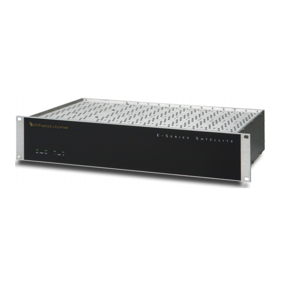
G E N E R A L I N F O R M A T I O N E-SAT - E-Series Satellite Digital Network Router The E-SAT is a rackmount unit occupying two 19” wide rack spaces (total height 3 1/2”) with 16” depth. The E-SAT accepts up to 16 discrete stereo analog or AES-3/SPDIF digital audio sources, and 16 stereo analog or digital outputs. -
Page 11: E-Series Micro Satellite Digital Network Router
G E N E R A L I N F O R M A T I O N E-Series Micro Satellite Digital Network Router MCS-8 The MCS-8 is a rackmount unit occupying one 19” wide rack space (total height 1 3/4”) with 16” depth. The MCS-8 accepts up to 8 discrete stereo analog or AES-3/SPDIF digital audio sources, and 8 stereo analog or digital outputs. -
Page 12: Mcs-8E
G E N E R A L I N F O R M A T I O N MCS-8E The MCS-8E is a rackmount unit occupying one 19” wide rack space (total height 1 3/4”) with 16” depth. The MCS-8E accepts up to 8 discrete stereo analog or AES-3/SPDIF digital audio sources, and 4 stereo analog or digital outputs. -
Page 13: Logic Connections
G E N E R A L I N F O R M A T I O N Logic Connections Input Ports SIMPLE INPUT EXAMPLE If a logic port is configured as an input (see settings for SW7 and SW8), the logic common setting for that port (SW4 and SW5) must be Common Plus. -
Page 14: Internal Programming Options
G E N E R A L I N F O R M A T I O N Internal Programming Options All internal programming options are made via PCB mounted switches. Switch Settings SW1 - AT Reset Momentarily pressing the switch resets the AT board LAN chip, while pressing and holding the switch also resets the FPGA. -
Page 15: E-Wheatnet- E-Series Audio Routing Switch Hub
G E N E R A L I N F O R M A T I O N S-16 E-WHEATNET - E-Series Audio Routing Switch S-16 E-WHEATNET is the high speed central network switch that connects up to sixteen studios from the technical operations center. S-16 E-WHEATNET is capable of simultaneously switching 64 bi-directional audio channels to 16 ports —... -
Page 16: I/O Connections
G E N E R A L I N F O R M A T I O N I/O Connections All audio network, master clock, and Ethernet connections are made via RJ-45 connectors mounted on the rear panel. The pinout drawings on page 1-10 summarize all wiring connections. -
Page 17: Ethernet Interface
Connect the S-16 E-WHEATNET to your Ethernet LAN with a straight (pin to pin) CAT5 cable. The LAN connection is for communicat- ing with computers running Wheatstone software such as XPoint, PC- XYC, and Event Computer. If you are connecting directly between the computer and the S-16 E-WHEATNET with no network in between, use a crossover cable. - Page 18 G E N E R A L I N F O R M A T I O N RJ-45 Connections Audio Network AES Clock SYNC TX + AES SYNC OUT HI TX - AES SYNC OUT LO RX + AES SYNC IN HI "1"-"16"...
-
Page 19: Front Panel Leds
G E N E R A L I N F O R M A T I O N Front Panel LEDs On the left-lower part of the front panel there are five LEDs, that function as follows. The “EXT” LED lights up when an external AES reference clock source is connected to the S-16 E-WHEATNET. -
Page 20: Jumper Settings
G E N E R A L I N F O R M A T I O N DIPSW2 Pos.1 (labeled DIPSWØ on the circuit board) - 48/44.1 Sample Rate - All devices in the Off = 44.1K, On = 48K system must be set to the same Pos.2 - reserved - never ON... -
Page 21: E-Wheatnet- E-Series Audio Routing Switch Hub
G E N E R A L I N F O R M A T I O N S-8 E-WHEATNET - E-Series Audio Routing Switch S-8 E-WHEATNET is the high speed central network switch that connects up to eight studios from the technical operations center. E- WHEATNET is capable of simultaneously switching 64 bi-directional audio channels to 8 ports —that’s 1024 traffic channels. -
Page 22: I/O Connections
G E N E R A L I N F O R M A T I O N I/O Connections All audio network, master clock, and Ethernet connections are made via RJ-45 connectors mounted on the rear panel. The pinout drawings on page 1-16 summarize all wiring connections. -
Page 23: Ethernet Interface
Connect S-8 E-WHEATNET to your Ethernet LAN with a straight (pin to pin) CAT5 cable. The LAN connection is for communicating with computers running Wheatstone software such as XPoint, PC-XYC, and Event Computer. If you are connecting directly between the computer and the S-8 E-WHEATNET with no network in between, use a crossover cable. - Page 24 G E N E R A L I N F O R M A T I O N RJ-45 Connections Audio Network AES Clock SYNC TX + AES SYNC OUT HI TX - AES SYNC OUT LO RX + AES SYNC IN HI "1"-"8"...
-
Page 25: Front Panel Leds
G E N E R A L I N F O R M A T I O N Front Panel LEDs On the right-lower part of the front panel there are five LEDs, that function as follows. The “EXT” LED lights up when an external AES reference clock source is connected to the S-8 E-WHEATNET. -
Page 26: Jumper Settings
G E N E R A L I N F O R M A T I O N DIPSW3 Pos.1 (labeled DIPSWØ on the circuit board) - 48/44.1 Sample Rate - All devices in the Off = 44.1K, On = 48K system must be set to the same Pos.2 - reserved - never ON... -
Page 27: E-Series Control Surfaces
G E N E R A L I N F O R M A T I O N E-Series Control Surfaces Designed to integrate flawlessly with the E-series Satellite digital audio network router, the E-series control surfaces allow you to easily create large- or small- platform-based systems that are exceptionally user- friendly and flexible. -
Page 28: Ethernet-Based Controllers
G E N E R A L I N F O R M A T I O N Ethernet-Based Controllers A family of Ethernet-based controllers provides an integrated way of switch- ing Digital Audio Router sources to destinations connected to the console. Rackmount and modular versions of the Ethernet based controllers are available. - Page 29 G E N E R A L I N F O R M A T I O N All X-Y crosspoint controllers have similar functions. First, select a DESTINATION (console fader, recorder, etc.) by turning the DESTINATION knob. By turning the SOURCE knob, the available inputs are displayed in the 8-character display window and the TAKE button lights.
-
Page 30: Audio Connections
G E N E R A L I N F O R M A T I O N Audio Connections All audio connections to the E-SAT and MICROSAT are made through multipin DB-25 connectors located on the rear of the chassis. The factory supplied hand crimping tool is used for all DB-25 style wiring connections (see instruction on the page 1-24). - Page 31 G E N E R A L I N F O R M A T I O N format converter when interfacing “consumer” grade source devices to the E-SAT. In cases where a consumer grade device must be interfaced and the appropriate matching device is not available, try wiring the SPDIF center conductor (HOT) to the HI input pin and SPDIF shell (ground) to the LO input.
-
Page 32: Hand Crimp Tool Wiring Instructions
G E N E R A L I N F O R M A T I O N HAND CRIMP TOOL WIRING INSTRUCTIONS The supplied hand crimping tool (W/S#850067) is used for all I/O wiring con- nections to and from the console. It is to be used with the supplied pin (figure 1) intended for 22"-28"... -
Page 33: Pin Extractor Instructions
G E N E R A L I N F O R M A T I O N PIN EXTRACTOR INSTRUCTIONS If you accidentally insert a crimp terminal pin into the wrong socket, you'll need to use the supplied pin extractor tool (W/S#850069) to remove terminal pin, and correct your mis- take without having to sacrifice a connector. -
Page 34: E-Series Digital Audio Netwok System Flow Diagram
E-Series Digital Audio Network System Flow Diagram page 1 - 26 E-Series Network / Jan 2008... - Page 35 H A R D W A R E Hardware Chapter Contents Overview ..................2-3 Configuration Guidelines ............. 2-3 Audio I/O Expansion ..................... 2-4 Digital Input Card (DI-NC4) Overview ........................2-5 AES Input Interface ....................2-5 Hook-Ups ........................2-6 DB Pinout Drawing ....................2-7 Analog Input Card (AI-NC4) Overview ........................
- Page 36 H A R D W A R E Dual Audio Network Card (AT-NC2) Overview ........................2-23 Internal Programming Options ................. 2-24 Switch Settings ......................2-24 Hook-Ups ......................... 2-25 Typical CAT5 Cable ....................2-25 RJ-45 Pinout Drawing ....................2-26 Digital Signal Processor Card (DSP-NC) Overview ........................
-
Page 37: Overview
Configuration Guidelines While the E-SAT router is pre-configured at Wheatstone’s factory, future expansion of a system may require some re-configuration of existing hardware to accommodate new resources. Slots are numbered from 1 to 12, left to right, as viewed from the rear of the cage. -
Page 38: Audio I/O Expansion
H A R D W A R E There are 12 ports on each logic card. Each logic card port may be configured as an input or output via an internal dipswitch selection. Analog and digital input and output cards each handle four stereo inputs/ outputs. -
Page 39: Digital Input Card (Di-Nc4)
H A R D W A R E Digital Input Card (DI-NC4) Overview The DI-NC4 digital audio input cards for the E-SAT and MICROSAT accept up to 4 AES-3 formatted stereo sources (i.e. 8 mono channels). An Audio Configuration form in the supplied XPoint software allows the user to set attributes for the input channels including signal name, location, and Stereo/ Mono. -
Page 40: Hook-Ups
H A R D W A R E Hook-Ups All user wiring to the DI-NC4 card takes place at the female DB-25 I/O connector on the cage rear. DB-25—Digital Audio Connections These include four input sources. Pinout drawing on page 2-8 shows all wiring connections at a glance. - Page 41 H A R D W A R E DI-NC4 Panel Digital Input Connections DB-25 Input Ports DIGITAL AUDIO GROUND INPUT AES 1 IN SH AES 1 IN LO AES 1 IN HI AES 2 IN SH AES 2 IN LO AES 2 IN HI AES 3 IN SH AES 3 IN LO...
-
Page 42: Analog Input Card (Ai-Nc4)
H A R D W A R E Analog Input Card (AI-NC4) Overview The Analog input card accepts up to 4 stereo analog audio sources (i.e. 8 mono channels). An Audio Configuration form in the supplied XPoint software allows the user to set attributes for the input channel hardware, including signal name, location, and Stereo/Mono. -
Page 43: Hook-Ups
H A R D W A R E Hook-Ups All user wiring to the AI-NC4 card takes place at the female DB-25 connector on the cage rear. DB-25—Analog Audio Connections These include four (1-4) input sources. Pinout drawing on page 2-11 shows all wiring connections at a glance. - Page 44 H A R D W A R E AI-NC4 Panel Analog Input Connections DB-25 Input Ports ANALOG AUDIO GROUND INPUT CHANNEL 1 (STEREO 1 LT) IN SH CHANNEL 1 (STEREO 1 LT) IN LO CHANNEL 1 (STEREO 1 LT) IN HI CHANNEL 2 (STEREO 1 RT) IN SH CHANNEL 2 (STEREO 1 RT) IN LO CHANNEL 2 (STEREO 1 RT) IN HI...
-
Page 45: Digital Output Card (Do-Nc4)
H A R D W A R E Digital Output Card (DO-NC4) Overview Each Digital Output card provides 4 physical AES-3 formatted outputs. An Audio Configuration form in the supplied XPoint software allows the user to set attributes for the output channels, including signal name, location, and Stereo/Mono. -
Page 46: Aes Channel Status Implementation
H A R D W A R E AES Channel Status Implementation The following embedded channel status information is transmitted at the AES digital outputs along with the audio data. Note: Channel Status bits are identically set for channels 1 and 2. CHANNEL STATUS: PROFESSIONAL DATA USE:... - Page 47 H A R D W A R E DO-NC4 Panel Digital Output Connections DB-25 Output Ports DIGITAL AUDIO GROUND AES 1 OUT SH OUTPUT AES 1 OUT LO AES 1 OUT HI AES 2 OUT SH AES 2 OUT LO AES 2 OUT HI AES 3 OUT SH AES 3 OUT LO...
-
Page 48: Analog Output Card (Ao-Nc4)
H A R D W A R E Analog Output Card (AO-NC4) Overview Each Analog Output card provides 8 physical monaural output channels. These output channels are configured in software to be 4 stereo pairs. An Audio Configuration form in the supplied XPoint software allows the user to set attributes for the output channels, including signal name, location, and Stereo/Mono. -
Page 49: Hook-Ups
H A R D W A R E Hook-Ups All user wiring from the AO-NC4 card takes place at the female DB-25 connector on the cage rear. Analog Audio Connections These include four outputs. Pinout drawing on page 2-17 shows all wiring connections at a glance. -
Page 50: External Mono Summing
H A R D W A R E External Mono Summing To sum an E-SAT or MICROSAT stereo analog output add a 1kOhm resistor in series with each leg of the balanced output. Add resistors as close as possible to the mono input. Example: AO-NC4 OUTPUT EXTERNAL DEVICE... - Page 51 H A R D W A R E AO-NC4 Panel Analog Output Connections DB-25 Output Ports ANALOG AUDIO GROUND OUTPUT CHANNEL 1 (STEREO 1 LT) OUT SH CHANNEL 1 (STEREO 1 LT) OUT LO CHANNEL 1 (STEREO 1 LT) OUT HI CHANNEL 2 (STEREO 1 RT) OUT SH CHANNEL 2 (STEREO 1 RT) OUT LO CHANNEL 2 (STEREO 1 RT) OUT HI...
-
Page 52: Overview
H A R D W A R E Logic Input/Output Card (LIO-NC4) Overview The LIO-NC4 is a programmable hardware interface with a feature set designed for broadcast studio control applications. Each Logic card provides twelve ports that may be programmed as inputs or outputs using SW1 -SW3 Default Setting dipswitches. -
Page 53: Output Ports
H A R D W A R E Output Ports Each of the twelve LH1522AB solid state relay outputs SIMPLE OUTPUT EXAMPLE may be configured in software to function as normally open EXT DEVICE or normally closed circuits when cross connected to an ROUTER input. -
Page 54: Software Programming
H A R D W A R E Software Programming For details on programming the LIO-NC4, please refer to “Configuring Logic I/O” in the XPoint Software Setup Guide later in this manual. Internal Programming Options All internal programming options are made via PCB mounted dipswitches and jumpers. - Page 55 H A R D W A R E Pin 8 – Logic 5 In/Out + Pin 21 – Logic 5 In/Out - Pin 7 – Logic 6 In/Out + Pin 20 – Logic 6 In/Out - Pin 6 – Logic 7 In/Out + Pin 19 –...
- Page 56 H A R D W A R E LIO-NC Panel Logic Input / Output Connections DB-25 Input/Output Ports LOGIC AUDIO GROUND I / O LOGIC 1 IN/OUT - LOGIC 1 IN/OUT + LOGIC 2 IN/OUT - LOGIC 2 IN/OUT + LOGIC 3 IN/OUT - LOGIC 3 IN/OUT + LOGIC 4 IN/OUT -...
-
Page 57: Dual Audio Network Card (At-Nc2)
H A R D W A R E Dual Audio Network Card (AT-NC2) Overview The Dual Audio Network card provides the audio and logic link between the central E-WHEATNET, the E-SAT, and optionally, a MICROSAT. All Audio Transport (AT) connections are made using UTP CAT-5 wired as crossover and terminated with RJ-45 connectors. -
Page 58: Switch Settings
H A R D W A R E Internal Programming Options All internal programming is done via PCB mounted switches. Switch Settings SW1 - Reset Momentarily pressing the switch resets the LAN chip, while pressing and holding the switch also resets the FPGA. DIPSW2 Pos.1 (labeled DIPSWØ... -
Page 59: Hook-Ups
H A R D W A R E Hook-Ups All user wiring to and from the AT-NC2 card’s LINK1 and 2 RJ-45 connectors is made using UTP CAT5 cable wired as crossover. For typical CAT5 cable pinouts see below. LINK 1 and 2 RJ-45—CAT5 Audio Network Connectors Pin 1 –... - Page 60 H A R D W A R E AT-NC Panel Network Connections LINK 1 - RJ-45 TXD + TXD - RXD + LINK RXD - LINK 2 - RJ-45 TXD + LINK TXD - RXD + RXD - page 2 – 26 E-Series Network / Apr 2007...
-
Page 61: Digital Signal Processor Card (Dsp-Nc)
Their fuctionality is determined by input and mix software which is loaded into each DSP card’s memory on surface powerup. Wheatstone’s XPoint software is used to map each DSP card to specific control surfaces and audio racks. Each input fader has a dedicated DSP channel which is responsible for gain, mode, phase, EQ, dynamics and metering. - Page 62 H A R D W A R E Hook-Ups All user wiring to and from the DSP-NC card’s LINK RJ-45 connector is made using UTP CAT5 cable wired as crossover. For typical CAT5 cable pinouts see below. LINK—CAT5 Audio Network Connectors Pin 1 –...
- Page 63 H A R D W A R E DSP-NC Panel Network Connections LINK - RJ-45 LINK TXD + TXD - RXD + RXD - page 2 – 29 E-Series Network / Apr 2007...
- Page 64 X P O I N T S O F T W A R E S E T U P G U I D E XPoint Software Setup Guide Chapter Contents E-WHEATNET Ethernet/IP Address Quick Start ......3-3 Ethernet Cabling ....................... 3-3 Default IP Address ....................
- Page 65 X P O I N T S O F T W A R E S E T U P G U I D E Main Menu Summary ..............3-25 File Menu ......................... 3-25 User Menu ....................... 3-25 Configure Menu ....................... 3-25 View Menu .......................
-
Page 66: E-Wheatnet Ethernet/Ip Address Quick Start
“on the air” without disruption; however it is always best to restrict configuration changes to time periods when an error could be tolerated. When in doubt, please contact Wheatstone Technical Service to avoid any error in configuration changes. E-WHEATNET Ethernet / IP... -
Page 67: Changing The E-Wheatnet's Ip Address
X P O I N T S O F T W A R E S E T U P G U I D E Changing the E-WHEATNET's IP Address Changing the IP address of devices in the system requires the editing of a text file located on the E-WHEATNET’s system CPU. -
Page 68: Getting Started
“online” faster. You may not need to make any software configuration changes. The XPoint software used to customize and configure the Wheatstone Network System is supplied with your system on CD-ROM. It is a Win- dows™ Graphical User Interface (GUI) program, intended to be straightfor- ward in use. -
Page 69: Gui Log-In
“New Password:” text box, then re-enter the password in the “Verify Password:” text box. Click “OK” to change the password or “Cancel” to cancel the operation. Custom users access may be created at the factory—contact Wheatstone sales. Password The default password is “Admin” for Adminis- trator. -
Page 70: Ip Addressing
Appendix 1 or contact Wheatstone Technical Support for details. System Configuration Menus From the user point of view, configuration of the Wheatstone E-Series Network system is relatively simple, since the Configuration GUI does much of the actual underlying configuration assignment work automatically. This section will outline a general procedure for configuring an E-Series Network system. -
Page 71: Tier Configuration
X P O I N T S O F T W A R E S E T U P G U I D E Tier Configuration Note that your system was pre-configured and this step is not necessary unless you have changed the IP address of the E-WHEATNET. Before you can connect to the system the Configuration GUI must be setup with some information regarding the E-WHEATNET’s network parameters. -
Page 72: E-Wheatnet Rack Configuration
X P O I N T S O F T W A R E S E T U P G U I D E E-WHEATNET Rack Configuration Note that your E-WHEATNET was pre-configured and this step is not necessary unless you are reconfiguring the system. Start up the Configuration GUI and log in to the software as Administrator. -
Page 73: E-Sat Rack Configuration
X P O I N T S O F T W A R E S E T U P G U I D E E-SAT Rack Configuration Note that your E-SAT racks are configured at the factory, and you do not have access to change configuration . -
Page 74: Visibillity Settings
X P O I N T S O F T W A R E S E T U P G U I D E Visibility Settings To view the control surface’s visibil- ity settings select Configure / E6 / Visibil- ity Settings menu option, which will display the form on the right. -
Page 75: Vdip Settings
X P O I N T S O F T W A R E S E T U P G U I D E VDip Settings To view or modify the Virtual Dip Switch Settings select the Configure / VDip Settings menu option, which will display the forms shown below. -
Page 76: Line Gain
X P O I N T S O F T W A R E S E T U P G U I D E • Machine Start Pulsed - This check box has no effect. • Remote Ready - Will control the channel’s OFF switch LED with a signal from an external source machine instead of it being controlled directly by the surface. -
Page 77: Programmable Buttons
X P O I N T S O F T W A R E S E T U P G U I D E Programmable Buttons The control surface’s programmable buttons can be used in different ways. If you want a button to fire a Salvo or make a temporary crosspoint, select the Configure / Spare Button LIOS menu, which will... - Page 78 X P O I N T S O F T W A R E S E T U P G U I D E Connection Between the Configuration GUI and E-WHEATNET While in OFFLINE mode, the GUI does not communicate to the Host CPU in the master rack.
- Page 79 X P O I N T S O F T W A R E S E T U P G U I D E Once the configuration has been downloaded the GUI enters the ONLINE state as shown to the left. Green Status Status...
- Page 80 X P O I N T S O F T W A R E S E T U P G U I D E To connect to the E-WHEATNET CPU while in OFFLINE mode, select the View / Mode / Online menu option. The status indicator on the screen will then change to CONNECTING as discussed above.
-
Page 81: Signal Definition
X P O I N T S O F T W A R E S E T U P G U I D E Signal Definition Up to 512 separate source and destination signals may be defined via the Configuration GUI (up to 2048 in multi-tier installations). To add or edit a signal from the GUI’s main grid, right click on one of the Source or Destination signals and select “Modify Signal Definition”. -
Page 82: Configuring Logic I/O
The LIO-NCA adds 12 programmable logic functions, configured individually as inputs or outputs, per card. The addition of logic I/O adds a powerful level of complexity to your Wheatstone router and care must be exercised during configuration to ensure the proper results. It is important to understand that there are two primary ways to configure the physical logic ports in software - routable logic or triggered ports. -
Page 83: Routable Logic Signal Definitions
X P O I N T S O F T W A R E S E T U P G U I D E Routable Logic Signal Definitions There are two types of routable logic signals - Logic I/O Only or Mapped Logic I/O. All routable logic signals must first be defined using the Signal Definitions form. -
Page 84: Defining Routable Logic Functions
X P O I N T S O F T W A R E S E T U P G U I D E Defining Routable Logic Functions Mapped logic and Logic I/O Only signals rely on common function names as a way of “knowing”... -
Page 85: Configured Triggered Port Logic
X P O I N T S O F T W A R E S E T U P G U I D E Configuring Triggered Port Logic Triggered logic ports enable the firing of salvos or temporary audio connections from a GPI or simple switch closure. When an input is configured to be a triggered port, its corresponding output is automatically assigned to be a Tally-back. -
Page 86: Signal Locking
X P O I N T S O F T W A R E S E T U P G U I D E Signal Locking To lock a signal, right click on the desired output channel on the crosspoint grid and select “Lock Connection”. -
Page 87: Salvo Definition
X P O I N T S O F T W A R E S E T U P G U I D E Salvo Definition Macro control of the E-WHEATNET is accomplished by creating and firing Salvos. A Salvo is simply a group of cross connects, disconnects and “do nothings”... -
Page 88: Main Menu Summary
X P O I N T S O F T W A R E S E T U P G U I D E Main Menu Summary The following is a summary of all the available menu choices when logged into XPoint as the Administrator. -
Page 89: View Menu
X P O I N T S O F T W A R E S E T U P G U I D E Microphone Gain : Make gain adjustments and enable/disable phantom power on mic inputs. Mix Minus Polarity : Set additive or subtractive mode. Passwords : Not used with E-Series surfaces. -
Page 90: Diagnostics Menu Examples
X P O I N T S O F T W A R E S E T U P G U I D E Diagnostics Menu Examples View TCP Connection Status Form: View System Integrity Form: page 3 – 27 E-Series Network / Apr 2007... -
Page 91: Analog Inputs Network I/O Center (Ainc-4)
S C H E M A T I C D R A W I N G S I/O Schematic Drawings Chapter Contents 4 Analog Inputs Network I/O Center (AINC-4) Schematic ......................... 4-2 Load Sheet ........................ 4-4 4 Analog Outputs Network I/O Center (AONC-4) Schematic ......................... - Page 92 R6 4.99K R65 4.99K 33pF -2dBu C102 33pF -2dBu LINE1LT_AI_LO R5 10.0K LINE3LT_AI_LO R64 10.0K 22uF 22uF C96 +4dBu BAL LINE1LT +4dBu BAL LINE3LT OP275 OP275 LINE1LT_AI_HI R4 10.0K LINE3LT_AI_HI R62 10.0K C101 0.001uF 0.001uF 33pF 4.99K 0.001uF 0.001uF 33pF 4.99K LINE 1 LINE 3...
- Page 93 1.00K 1.00K 1.00K 1.00K 0.001uF C124 0.001uF C114 0.001uF C128 0.001uF C120 BAT54 BAT54 VA+_1 VA+_3 BAT54 BAT54 3V_1 VA+_1 3V_1 3V_3 VA+_3 3V_3 LINE1LT R78 2.32K LINE3LT R90 2.32K 0.001uF 0.001uF OP275 OP275 OP275 OP275 4.99K 4.99K 10uF .1uF C113 10uF .1uF...
- Page 94 S C H E M A T I C D R A W I N G S 4 Analog Inputs Network I/O Center (AINC-4) - Load Sheet page 4 – 2 page 4 – 4 E-Series Network / Apr 2007...
- Page 95 -2dBu -2dBu LINE1LT_AO_HI LINE3LT_AO_HI +3.3V +3.3V +3.3V +3.3V +3.3V +3.3V OUTPT1LT OUTPT3LT +4dBu BAL +4dBu BAL LINE1LT_AO_LO LINE3LT_AO_LO SSM2142 SSM2142 4.99K 4.99K 4.99K 4.99K DIF0 68pF 68pF 68pF 68pF DIF1 LINE 1 LINE 3 DIF2 DEM0 DEM1 -2dBu -2dBu MUTE LINE1RT_AO_HI LINE3RT_AO_HI OUTPT1RT...
- Page 96 3V_12 3V_12 VA_12 3V_34 3V_34 VA_34 47uF C26 47uF 47uF C28 47uF 1.00K 1.00K DVDD AVDD 2.00K 5.76K DVDD AVDD 2.00K 5.76K DIF0 DIF0 390pF 390pF DIF0/DCLK VREFH DIF0/DCLK VREFH DIF1 DIF1 DIF1/DSDL DIF1/DSDL DIF2 -2dBu DIF2 -2dBu 3900pF 3900pF DIF2/DSDR AOUTL- DIF2/DSDR...
- Page 97 S C H E M A T I C D R A W I N G S 4 Analog Outputs Network I/O Center (AONC-4) - Load Sheet page 4 – 3 page 4 – 7 E-Series Network / Apr 2007...
- Page 98 +3.3V +3.3V +3.3V +3.3V +3.3V 22uF 0.1uF 1.00K TDM_I VDD_IO LINE1_DI_LO 1.00K SDOUT SDATA_I SDATA_O C11 0.1uF LINE1_DI_HI RXP0 OSCLK SCLK_I SCLK_O RXP1 OLRCK LRCLK_I LRCLK_O RXP2 +3.3V +3.3V +3.3V +3.3V +3.3V +3.3V RXP3 SMODE_I_0 RXSEL1 SMODE_I_1 RXSEL0 RMCK SMODE_I_2 1.00K 4.99K 1.00K...
- Page 99 +3.3V +3.3V +3.3V +3.3V +3.3V 22uF 0.1uF 1.00K TDM_I VDD_IO LINE3_DI_LO 1.00K SDOUT SDATA_I SDATA_O 0.1uF LINE3_DI_HI RXP0 OSCLK SCLK_I SCLK_O RXP1 OLRCK LRCLK_I LRCLK_O RXP2 +3.3V +3.3V +3.3V +3.3V +3.3V +3.3V RXP3 SMODE_I_0 RXSEL1 SMODE_I_1 RXSEL0 RMCK SMODE_I_2 1.00K 4.99K 1.00K TXSEL1...
- Page 100 S C H E M A T I C D R A W I N G S 4 Digital Inputs Network I/O Center (DINC-4) - Load Sheet page 4 – 4 page 4 – 10 E-Series Network / Apr 2007...
- Page 101 +3.3V +3.3V +3.3V +3.3V +3.3V +3.3V +3.3V +3.3V +3.3V +3.3V +3.3V +3.3V 4.99K 4.99K 4.99K 4.99K 4.99K 4.99K 4.99K 4.99K ADO_SDATA1 ADO_SDATA3 SDIN SDIN XDO_SCLK XDO_SCLK ISCLK ISCLK ILRCK ILRCK TEST TEST TEST TEST TEST TEST HWCK1 HWCK1 DO_CBL DO_CBL HWCK0 TCBL HWCK0...
- Page 102 S C H E M A T I C D R A W I N G S 4 Digital Outputs Network I/O Center (DONC-4) - Load Sheet page 4 – 5 page 4 – 12 E-Series Network / Apr 2007...
- Page 103 1.00K 1.00K +3.3V +3.3V +3.3V +3.3V +3.3V +3.3V LIODB_1 LIODB_7 LIODB_1 LIODB_7 1.00K 1.00K DB-25 CONNECTOR 4.99K 0.1uF 4.99K 0.1uF 2 AQW210S 2 AQW210S 2 AQW210S AQW210S AGND LIODB_1 LIODB_2 1.00K 1.00K +3.3V +3.3V LIODB_3 +3.3V +3.3V +3.3V +3.3V LIODB_2 LIODB_8 LIODB_4 LIODB_5...
- Page 104 +3.3V +3.3V FPGA_TDI VCCJ VCCO NOT INSTALLED PROMDATA CCLK ____ INIT OE/RST ____ DONE _________ XCF01 PROGRAM +3.3V R41 4.99K CCLK +3.3V CCLK DONE DONE FPGA_TDI DIP_LIO_3 DIP_LIO_4 NOT INSTALLED I/O,Vref0 LIO_FS +3.3V +3.3V DIP_LIO_5 LIO_ID I/O,Vref0 I/O,Vref5 1.00K 10.0K 1.00K DIP_LIO_6 GCK3,I...
- Page 105 S C H E M A T I C D R A W I N G S Logic Interface Network I/O Center (LIONC-12) - Load Sheet page 4 – 6 page 4 – 15 E-Series Network / Apr 2007...
- Page 106 RJ-45 CONN AT "A" RJ-45 CONNECTOR AGND AGND A_RJ_P2 A_AT_TX- A_RJ_P8 R43 47 C18 0.1uF A_RJ_P8 R40 68 +5VDin +5VDin A_RJ_P7 +5VDin +5VDin A_RJ_P7 A_RJ_P1 A_AT_TX+ A_RJ_P6 RXD- ADO_SPARE ETSP_MIXO3 A_RJ_P5 C49 0.01uF DO_CBL ETCTL_MIXO2 AGND A_RJ_P4 DO_C ET_MIXI4 ET_MIXI3 A_RJ_P3 A_RJ_P6 A_AT_RX-...
- Page 107 ENB_24 XTAL_CLK R129 24.576MHZ +3.3V 4.99K ENB_22 R130 22.5792MHZ 4.99K +3.3V 4.99K AT_RESET_SW +3.3V PROGRAM_B CCLK R99 100 R105 47 CCLK DIPSW_1 DONE R131 DONE DIPSW_2 4.99K DIPSW_3 44_48 DIPSW_4 R16 1.00K FPGA_TDI HSWAP_EN R12 3.3 NOT INSTALLED I/O,L01P_7/VRN_7 I/O,L01N_7/VRP_7 I/O,L01N_2/VRP_2 +3.3V +3.3V...
- Page 108 S C H E M A T I C D R A W I N G S Dual Audio Transport Network I/O Center (ATNC-2) - Load Sheet page 4 – 7 page 4 – 18 E-Series Network / Apr 2007...
- Page 109 S C H E M A T I C D R A W I N G S Digital Signal Processor Card (DSP-NC) - Load Sheet page 4 – 8 page 4 – 19 E-Series Network / Apr 2007...
- Page 110 LOGIC I/O 1-12 LOGIC I/O 13-24 INPUT 1-4 INPUT 5-8 INPUT 9-12 INPUT 13-16 CT10 CT11 CT12 AGND AGND AGND AGND AGND AGND AGND AGND AGND AGND AGND AGND V-in V-in V-in V-in V-in V-in V-in V-in V-in V-in V-in V-in V+in V+in...
- Page 111 SAT-E Mother Board (MBNC-1) - Load Sheet page 4 – 21 E-Series Network / Apr 2007...
- Page 112 S-16 Wheatnet-E Super Hub Main Card (IB-1) - Load Sheet page 4 – 22 E-Series Network / Apr 2007...
- Page 113 S C H E M A T I C D R A W I N G S S-16 Wheatnet-E Super Hub LED Card (IBEL-1) - Load Sheet page 4 – 9 page 4 – 23 E-Series Network / Apr 2007...
- Page 114 S-8 Wheatnet-E Super Hub Main Card (IBA-1) - Load Sheet page 4 – 24 E-Series Network / Jan 2008...
- Page 115 Micro Satellite Main Card (MCS-8 & MCS-8E) - Load Sheet page 4 – 25 E-Series Network / Jan 2008...
- Page 116 G L O S S A R Y Glossary The terminology used in this manual is defined as follows. • Channel - A single, monaural audio stream. The E-SAT can switch up to 32 discrete inputs to 32 discrete outputs (16 x 16 stereo) per tier. •...
- Page 117 A P P E N D I C E S Appendices Appendix 1 Configuring System IP Addresses ..........A-3 Overview ........................A-3 Editing Network Parameters ..................A-3 Setting up FTP Site Profiles ................A-3 Editing the Network Text Files ................A-4 Sample E-WHEATNET CPU Network File ............
- Page 118 A P P E N D I C E S Appendix 1 Contents Configuring System IP Addresses ..........A-3 Overview ........................A-3 Editing Network Parameters ..................A-3 Setting up FTP Site Profiles ................A-3 Editing the Network Text Files ................A-4 Sample E-WHEATNET CPU Network File ............
-
Page 119: Configuring System Ip Addresses
Caution! Your system has been pre-configured at the factory for a default IP address of 192.168.1.160. Incorrect editing of network files will cause system malfunction. Please consult Wheatstone support if you are having trouble connect- ing your system to a network. -
Page 120: Editing The Network Text Files
A P P E N D I C E S Editing the Network Text Files Note: It is very important to save the edited file on your PC. This can help in the event a typo prevents you from connecting after re-boot. Once connected via FTP to the E-WHEATNET’s flash hard drive you will see a directory listing of files and an FDOS folder. - Page 121 Exceptions are those controls and components that in the course of normal use may need maintenance. A complete list of available compo- nents follows. Contact Wheatstone technical support for further infor- mation. Wheatstone Corporation (600 Industrial Drive, New Bern, North Carolina, USA 28562) may be reached by phone at 252-638-7000, fax 252-637-1285, electronic mail “techsupport@wheatstone.com”.
- Page 122 A P P E N D I C E S REPLACEMENT PARTS — S-16 E-WHEATNET COMPONENT DESCRIPTION WS P/N IBE-1NC LOADED CARD PROCESSOR LOADED CARD ASSEMBLY W/O COMPUTER "009803" "009801" IBEL-1 LOADED CARD LED LOADED CARD ASSEMBLY POWER CORD 7 1/2' BLACK POWER CORD "150017"...
- Page 123 A P P E N D I C E S REPLACEMENT PARTS — S-8 E-WHEATNET COMPONENT DESCRIPTION WS P/N IBA-1NC LOADED CARD PROCESSOR LOADED CARD ASSEMBLY W/O COMPUTER "008498" "150017" POWER CORD 7 1/2' BLACK POWER CORD I/O CONNECTOR 8 GANG RJ45 ASSEMBLY WITH GREEN/YELLOW LED "220137"...
- Page 124 A P P E N D I C E S REPLACEMENT PARTS — E-SATELLITE COMPONENT DESCRIPTION WS P/N AI-NC4 LOADED CARD ANALOG INPUT CARD ASSEMBLY "008810" AO-NC4 LOADED CARD ANALOG OUTPUT CARD ASSEMBLY "008811" DI-NC4 LOADED CARD DIGITAL INPUT CARD ASSEMBLY "008812"...
- Page 125 A P P E N D I C E S REPLACEMENT PARTS — MICROSATELLITE MCS-8 COMPONENT DESCRIPTION WS P/N AI-NC4 LOADED CARD ANALOG INPUT CARD ASSEMBLY "008810" "008811" AO-NC4 LOADED CARD ANALOG OUTPUT CARD ASSEMBLY DI-NC4 LOADED CARD DIGITAL INPUT CARD ASSEMBLY "008812"...
- Page 126 A P P E N D I C E S REPLACEMENT PARTS — MICROSATELLITE MCS-8E COMPONENT DESCRIPTION WS P/N AI-NC4 LOADED CARD ANALOG INPUT CARD ASSEMBLY "008810" AO-NC4 LOADED CARD ANALOG OUTPUT CARD ASSEMBLY "008811" DI-NC4 LOADED CARD DIGITAL INPUT CARD ASSEMBLY "008812"...
Need help?
Do you have a question about the Evolution Series and is the answer not in the manual?
Questions and answers