
Summary of Contents for CMR Electrical LD32
- Page 1 CMR Electrical Ltd Bolton House Five Chimneys Lane Hadlow Down East Sussex TN22 4DX Tel: 01825 733600 LD32 Water Leak Detection Manual...
- Page 2 Contents 1) System Overview 2) Display and Control 3) Water Detected Alarm 4) Sensor Fault Alarm 5) Relay outputs 6)“Mute” push button 7) “Light” push button 8) “Info” push button 9) Beacon and beacon sounder 10) Fitting SCA repeat alarm or SMS / Email messaging system 11) Outstation 12) Positioning the Outstations 13) Fitting and wiring Alarm unit...
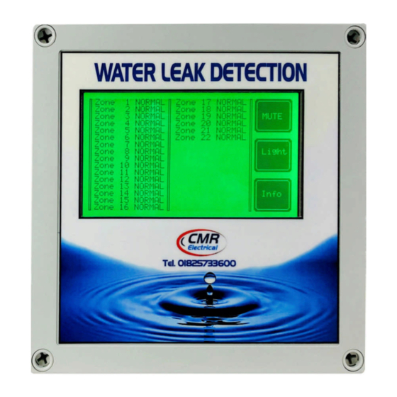
- Page 3 1) System Overview The unit has been designed to interrogate individual outstations and report back to the main controller if water or a disconnected sensor is found. On powering up, the unit will display “SETTING UP PLEASE WAIT” until all remote outstations have been interrogated for their current status. Providing there are no alarms or faults on the system, the displays backlight will change to green and all zones will be shown as “NORMAL”.
- Page 4 2) Display and Control Screen 1 Screen 2 Normal, no alarm or faults Unacknowledged (new) water leak detected Screen 3 Screen 4 Acknowledged water detected alarm Unacknowledged (new) Cable fault Screen 5 Screen 6 System information Acknowledged Cable fault 3) Water Detected Alarm When the detection cable comes into contact with water anywhere along its length, the audible warning device will start, the New alarm and common alarm relay will operate and display will start flashing with the zone number.
- Page 5 5a) Outstation common alarm relay Each outstation has its own common alarm relay for just the zones fitted to the outstation. Located on the top left of the outstation board (see above) use the two terminals provided. Note; this contact is only Normally open, Close in alarm. 6)“Mute”...
- Page 6 10) Fitting SCA repeat alarm or SMS / Email messaging system Use the “SMS” terminal block Cable wire colours fitted Terminal Terminal to the messaging system BLUE BLACK 11) Outstation Standard outstation “Active” communication to Outstation number alarm unit healthy light Zone water &...
- Page 7 12) Positioning the Outstations All outstations are wall mounted using the fixing points located in each corner behind the removable front cover. Outstations should be mounted in a position to allow accessibility to the internal components and cables. 13) Fitting and wiring Alarm unit Main control unit THIS EQUIPMENT SHOULD ONLY BE CONNECTED AND WORKED ON BY A QUALIFIED ELECTRICIAN.
- Page 8 Output Volt Free contacts for use by a Building Management System. Function Required Function New alarm Operates on each new water leak alarm or sensor fault, reset by muting Common Alarm Any zone in water alarm, clears with no water alarms on the system Common Fault Operates on disconnected sensor or power fault (See Item 5 above)
- Page 9 Stannard Outstation Valve control Outstation Connect a 230VAC supply to terminals Water detection sensor wiring RS485 terminal block layout Only the Red and Black Sc|A|B|0V|+V cables in the white signal Control unit Outstation cable are used. (Screen wire) Red wire Sig+ (wire 1) Black wire...
- Page 10 17) Fitting Cable Clips If Cable Clips are required, to protect the small sensor wires and to stop false water detected alarms from occurring insulating tape should be first applied around the detection cable before the clip tongue is closed. Clips should be fitted approximately every 1 to 1.5 metres apart. When using clips make sure that the cable touches the floor between the clips, DO NOT tighten the cable so that the cable does not touch the floor.
- Page 11 PLEASE NOTE; We don’t recommend that this type of valve and will NOT be supplied by CMR electrical. However, if this type of valve MUST be fitted, ensure that the arrow on its body facing the direction of flow, if not, the valve will not stop the flow of water.
- Page 12 22) Commissioning Having connected the unit as described above, turn on the mains power to the unit. The screen should display “Setting up please wait”, If not, refer to the “Fault Diagnostics” below. If the unit powers up with the audible warning going, press the mute button and wait to see if the alarm clears. If the alarm remains after approximately 10 seconds, refer to the “Fault Diagnostics”...
- Page 13 24) Fault Diagnoses “Active” LEDS are provided on all outstations and the main alarm unit. The lights are provided to help when fault finding. When all interconnecting cabling is correct, the alarm unit “Active” LED should look to ON and all the outstation “Active” LEDS should be flashing. If the alarm units LED is OFF, it indicates that the controller can communicate to any of the outstations.
- Page 14 25) Installation Drawings 120R 3 core 0.22mm 12VDC cable...
Need help?
Do you have a question about the LD32 and is the answer not in the manual?
Questions and answers