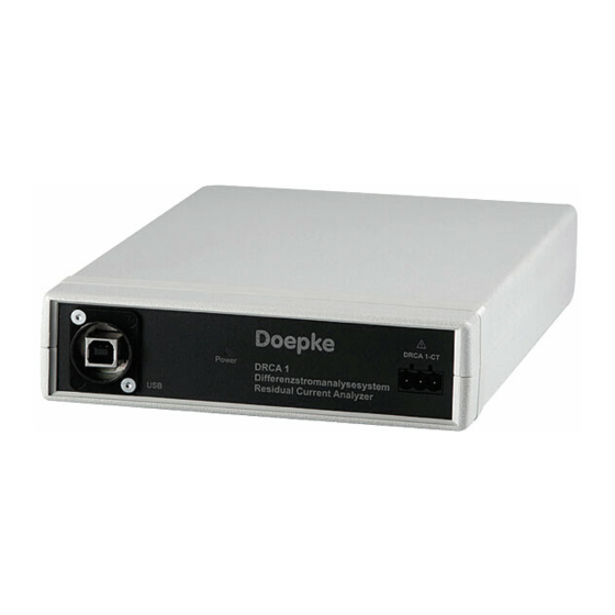
Summary of Contents for Doepke DRCA 1
- Page 1 Doepke www -- -- -- -- - doepke.de Residual current analysis system DRCA 1 Instructions for use and technical information Residual current analysis DRCA 1...
- Page 2 October 2019 The use of this document is solely at your own discretion. Doepke Schaltgeräte GmbH accepts no liability for any damages arising from the use of this document, in particular breakdown of operations, loss of earnings, loss of information and data or consequential damages, except in cases of compulsory liability, e.g.
-
Page 3: Table Of Contents
Content page 24 The DRCA 1 residual current analysis system Installation requirements –––––––– –––––––––– –––––––––– ––––––––––– –––––––––– –––––––––– –––––––– Connection to the power supply ––– –––––––––– –––––––––– ––––––––––– –––––––––– –––––––––– –––– page 24 page 6 Intended use of the device – – –– – –– – –– –– – –– – –– – –– – –– – –– – –– – –– – –– – –– – –– – –– – –– – –– – –– – –– – –– –– – –– Ventilation and cooling ––––––––––... -
Page 4: The Drca 1 Residual Current Analysis System
The residual current transformer is to be permanently installed when the distribution board is free from voltage. The DRCA 1-MC cable is to be used for measurement. The installation of the transformer must only be performed by qualified electricians. -
Page 5: Main Menu
– Choose Productgroup (selection of Doepke products to be used as basis for evaluation) Note � � �� � �� �� � �� � �� � The 'Quit DRCA 1' button closes the program and all previously opened submenus. The results of Data Storage are retained. 8 / 9... -
Page 6: General Signal Analysis
GENERAL SIGNAL ANALYSIS 5. General signal analysis The 'Screenshot' button has been added for documentation purpos- es. When this button is pressed, an image of the screen is saved. The user is informed of the save location and the file names used. Current Waveform RMS Values Fig. -
Page 7: Frequency Analysis
GENERAL SIGNAL ANALYSIS Frequency Analysis Note � �� � �� �� � �� � �� �� If, for example, a trigger level of 300 mA is set and enabled, a residual current of 200 mA would no longer be displayed. In order to avoid erroneous measurement, the trigger is therefore disabled by default. -
Page 8: Triggermode
DATA STORAGE 6. Data Storage Triggermode The 'Trigger' module was developed to enable recording of switch-on and switch-off processes. Signals that only exist for a short time and In addition to the values shown in chapter 5.2 ('RMS value diagram'), have steep edges cannot be recognised in other programs, as they the peak value determined in each measurement cycle is also saved. -
Page 9: Read Rms Values
DATA STORAGE As soon as the measurement is started, all elements are blocked to the user, except for 'Cancel Storage'. The measurement ends automatically once the 'Measurement end time' is reached, although it can be ended before this using 'Early termination'. Data recorded up to this point is saved. -
Page 10: Rated Analysis
DCTR B DMRCD 1 B+ DRCM 1 B+ produced by Doepke Schaltgeräte GmbH are available, which can measure the residual current to be evaluated. As the program operation for each product group is identical, the function is explained using one selected group (DFS 4 B). -
Page 11: Explanation Of Rated Analysis
Types with tripping currents of 100 mA can be seen in the tripping frequency response in Fig. 17. Further information on this topic can also be found in Doepke's brochure: 'AC-DC sensitive residual current devices: RCD Type B'. -
Page 12: Colour Coding
If several programs are open at the same time, interruptions may Double the sampling frequency is required for meaningful sampling occur during the measurement. of a signal that is continuous over time. The DRCA 1 uses a sampling rate of greater than 200 kHz. Therefore, the maximum frequency that Switch selection after RCD overview can be recorded is around 100 kHz. -
Page 13: Rating Data
The USB cable, which is connected to the PC/notebook, is connected hazard point. All connections for measuring devices in category I are via a USB socket. The transformer is connected to the DRCA 1-CT labelled in this way. socket with the supplied DRCA 1-MC measuring cable. -
Page 14: Measurement Category
AC: up to 10 A peak-to-peak value, Measuring range DC: not measurable DRCA 1-CT transducer Rated current DRCA 1-CT 70 200 A when residual current I = 100 mA 10 Hz - 100 kHz: ± 1 dB Accuracy when I = 100 mA... - Page 15 T - - --- - - ---- ------ +49 (0) 49 31 18 06-0 +49 (0) 49 31 18 06-101 F - -- - - - --- - ------- www - -- ----- doepke.de article number 59 625 11 | state 10/2019...


Need help?
Do you have a question about the DRCA 1 and is the answer not in the manual?
Questions and answers