Advertisement
Quick Links
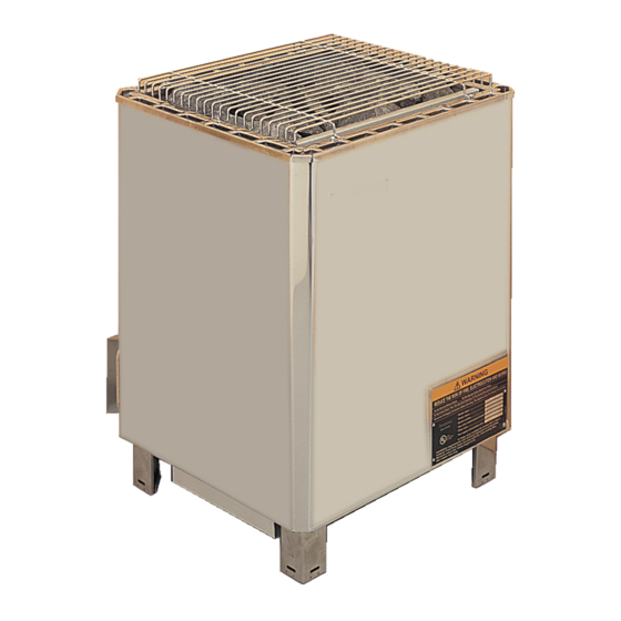
INSTALLATION AND OPERATING INSTRUCTIONS
Pro Heater
1105-XXX
Laava Heater
1105-XXX2
Octa Heater
1106
Pro 10.5, 12.0, & 14.4
Laava 10.5, 12.0, & 14.4
Octa 10.5, 12.0, & 14.4
(With separate Digi Control panel & contactor box)
Read all instructions carefully before installation. Please
leave all instructions and warranty with the owner.
WARNING
Prolonged exposure to elevated temperatures is capable of inducing
hyperthermia. Hyperthermia occurs when the internal temperature of
the body reaches several degrees above the normal body temperature of
98.6°F. The symptoms of hyperthermia include an increase in the
normal temperature of the body, dizziness, lethargy, drowsiness, and
fainting. The effects of the hyperthermia include failure to perceive
heat, failure to recognize the need to exit the room, unawareness of
impending hazard, fetal damage in pregnant women, physical inability
to exit the room and unconsciousness.
WARNING
The use of alcohol, drugs, or medication is capable of greatly
increasing the risk of fatal hyperthermia.
SECTION 1: GENERAL INFORMATION
These heaters are ETL approved by Intertek for permanent installations.
All wiring must be performed in accordance with the NEC and local
codes. See Table 1 for wire and room size requirements.
These heaters are free standing, secured to the floor, with separate
controls.
4211-89-G
12/03/18
Contactor
Box
CB 9-1 or
CB 9-3
prog ok
Digi I
(Model # 1105-105, 1105-120 & 1105-140)
(Model # 1105-1052, 1105-1202 & 1105-1402)
(Model #1106-105, 1106-120, & 1106-140)
Do not take a sauna if using
1
prog ok
2
3
4
Digi VII
Pregnant women or persons
consult their physician before
1
prog ok
2
Caution fire hazard: Do not
3
4
drying clothes, bathing suits,
Digi II
object other than the rocks
supplied on the heater. If any
darkening of the wall around
Inspect sauna regularly for
heater, control and benches.
Replace wood surfaces which
The heater gets extremely hot
during operation and should
not be touched or burns may
Minors should be adequately
supervised whenever near a
Page 1
WARNING
alcohol, drugs or
medications.
with poor health should
using any sauna.
use the sauna room for
etc. Do not hang towels
above heater or place any
the heater is noticed
discontinue sauna use
immediately.
required maintenance to
show any signs of
deterioration.
result.
hot or warming sauna.
314 SKLE 69
I
7014023
Advertisement

Summary of Contents for TylöHelo Pro Series
-
Page 1: Section 1: General Information
INSTALLATION AND OPERATING INSTRUCTIONS Page 1 WARNING Pro Heater Contactor 1105-XXX Do not take a sauna if using CB 9-1 or alcohol, drugs or prog ok Laava Heater CB 9-3 medications. 1105-XXX2 Digi VII Pregnant women or persons with poor health should consult their physician before using any sauna. - Page 2 INSTALLATION AND OPERATING INSTRUCTIONS Page 2 SECTION 2: MOUNTING OF SAUNA HEATER WARNING Carefully locate the heater according to the dimensions shown in Fire sprinkler systems used Diagram 1 and bolt it to the floor. (Bolts are not supplied with the inside any sauna room heater.) Tighten to secure the heater in place.
- Page 3 INSTALLATION AND OPERATING INSTRUCTIONS Page 3 DIAGRAM 1 Pro Heater Model # 1105-XXX High Limit Control Reset 2" 5" 1x1" min. wooden 2½" post Sensor 49½" 5" min. min. min. ¾ x 4" wooden 78" 2½" rail min. min. 27" max.
- Page 4 INSTALLATION AND OPERATING INSTRUCTIONS Page 4 DIAGRAM 1 Laava Heater 1105-XXX2 High Limit Control Reset 2" 4-1/2" 1x1" min. wooden 1" post Sensor 49½" 2" min. min. min. ¾ x 4" wooden 78" 1" rail min. min. 27" max. OBSERVING MINIMUM DISTANCES IS REQUIRED TO REDUCE THE RISK OF FIRE BOLTS Locate the sensor 2"...
- Page 5 INSTALLATION AND OPERATING INSTRUCTIONS Page 5 DIAGRAM 1 Continued Octa Heater Model # 1106-XXX 2" High Limit Control Reset " 1x1" 46¾" min. Sensor wooden ¾ " post min. " min. 78" min. ¾ ¾ x 4" " wooden min. rail 30"...
- Page 6 INSTALLATION AND OPERATING INSTRUCTIONS Page 6 TABLE 1 Minimum Room Maximum Room Copper Wire Size 90° C Heater Power Contactor Light Circuit Model / Floor Wall Volume Wall Volume Contactor ** Breaker Supply to Contactor to Heater Contactor to or Fan Product Area Height...
- Page 7 INSTALLATION AND OPERATING INSTRUCTIONS Page 7 DIAGRAM 4 SINGLE PHASE WIRING DIAGRAM HEATER MODELS: Pro 10.5, 12.0 & 14.4 Model Number: 1105-105, 1105-120 & 1105-140 Laava 10.5, 12.0 & 14.4 Model Number: 1105-1052, 1105-1202 & 1105-1402 208V or 240V 1-phase CONTACTOR BOX CB 9-1 (Model # 1201-9-1) Circuit 1...
- Page 8 INSTALLATION AND OPERATING INSTRUCTIONS Page 8 DIAGRAM 4, Continued THREE PHASE WIRING DIAGRAM HEATER MODELS: Pro 10.5, 12.0 & 14.4 Model Number: 1105-105, 1105-120 & 1105-140 Laava 10.5, 12.0 & 14.4 Model Number: 1105-1052, 1105-1202 & 1105-1402 208V or 240V 3-phase CONTACTOR BOX CB 9-3 (Model # 1201-9-3)
- Page 9 INSTALLATION AND OPERATING INSTRUCTIONS Page 9 DIAGRAM 4, Continued Single Phase Wiring Diagram: Heater Models Octa 10.5, 12.0 & 14.4 Model Number: 1106-105, 1106-120 & 1106-140 208V or 240V 1-phase CONTACTOR BOX CB 9-1 (Model # 1201-9-1) Circuit 1 Circuit 2 Fan Circuit Light Circuit 120 Watt Max Light Circuit...
- Page 10 INSTALLATION AND OPERATING INSTRUCTIONS Page 10 DIAGRAM 4, Continued Three Phase Wiring Diagram: Heater Models Octa 10.5, 12.0 & 14.4 Model Number: 1106-105, 1106-120 & 1106-140 208V or 240V 3-phase CONTACTOR BOX CB 9-3 (Model # 1201-9-3) Circuit 1 Fan Circuit Light Circuit 120 Watt Max Light Circuit 120 Watt Max Fan Circuit...
-
Page 11: Section 7: Operation
INSTALLATION AND OPERATING INSTRUCTIONS Page 11 SECTION 7: OPERATION WARNING The control for this heater has a thermostat to adjust the sauna Do not locate benches over temperature and a timer to control when the heater starts and stops. The heater. -
Page 12: Language [English]
INSTALLATION AND OPERATING INSTRUCTIONS Page 12 SECTION 7: OPERATION, DIGI VII The Digi VII 24 hr (Model # 1601- 15-1) control model can be set to stay on longer than 60 minutes. This is for commercial use only where an attendant is present. - Page 13 INSTALLATION AND OPERATING INSTRUCTIONS Page 13 SECTION 7: OPERATION, DIGI VII CONTINUED Next will display: MENU 4 OFFSET: T1 0C Using the arrow keys, select the calibration value (0 +/-10C). Example: After reading the temperature on the thermometer in the sauna, you may have noticed that the temperature reading on the sauna thermometer is lower than the display on the control.
- Page 14 INSTALLATION AND OPERATING INSTRUCTIONS Page 14 SECTION 7: OPERATION, DIGI VII CONTINUED Changing Sauna Length of Operation To change the sauna length time press the Sauna Heat Time button and the hours and minutes (hh:mm) will appear in the display. On Time 1:00 The time can now be set using the arrow keys. When the desired time has been selected, press PROG/OK to return to previous screen.
- Page 15 INSTALLATION AND OPERATING INSTRUCTIONS Page 15 SECTION 7: OPERATION, DIGI II The Digi II 24 hr (Model # 1601- 11-1) control model can be set to stay on longer than 60 minutes. This is for commercial use only where an attendant is present. Increase On/Off Temperature...
- Page 16 INSTALLATION AND OPERATING INSTRUCTIONS Page 16 SECTION 7: OPERATION, DIGI II CONTINUED Next will display: MENU 3 OFFSET: T1 0C Using the arrow keys, select the calibration value (0 +/-10C). Example: After reading the temperature on the thermometer in the sauna, you may have noticed that the temperature reading on the sauna thermometer is lower than the display on the control.
- Page 17 INSTALLATION AND OPERATING INSTRUCTIONS Page 17 SECTION 7: OPERATION, DIGI II CONTINUED Programming Memory (User buttons) continued... Press the TEMPERATURE button and the temperature value will appear in the display current temperature setting: 156F The temperature can now be set using the arrow keys. When the desired temperature has been selected, press PROG/OK and the display will return to the previous screen.
- Page 18 INSTALLATION AND OPERATING INSTRUCTIONS Page 18 SECTION 7: OPERATION, DIGI II CONTINUED Setting Time Delay with Saunasmart: Saunasmart means choosing the time to enter the hot room, not the time to turn the heater on. The system will calculate when to turn on in relation to entry time. The control will be able to determine how long the system needs to run to reach set temperature.
- Page 19 INSTALLATION AND OPERATING INSTRUCTIONS Page 19 SECTION 7: OPERATION, DIGI I Control Model Digi I 60 min (Model # 1601-14): Light Increase Temperatu Sauna Length Delay Start On/Of Decrease The 1601-14-1 control model can be set to stay on longer than 60 minutes.
- Page 20 INSTALLATION AND OPERATING INSTRUCTIONS Page 20 SECTION 7: OPERATION, DIGI I CONTINUED Control Setup for Digi I 60 min Control (Model # 1601-14): Setting Temperature Scale: The control in the Off mode: Press ON/OFF FAHR will appear. Press the Up button to toggle between Fahrenheit and Celsius. Press OK when the appropriate scale is displayed.
- Page 21 INSTALLATION AND OPERATING INSTRUCTIONS Page 21 SECTION 8: LIMIT CONTROL (RESET BUTTON) The sauna heater has a built-in High Limit control, which automatically turns off the heater if the temperature inside in the sauna room rises to an abnormally high level. To restart the heater, let the heater cool and the timer run down to zero (off), then push the reset button on the bottom of the heater, See Diagram 1.
- Page 22 INSTALLATION AND OPERATING INSTRUCTIONS Page 22 SECTION 11: ROOM CONSTRUCTION The "CAUTION" and "WARNING" placards must For safety and reliability, the following rules must be addressed. be mounted in accordance • No permanent locking or latch system is to be used on the sauna with Section 10.
- Page 23 INSTALLATION AND OPERATING INSTRUCTIONS Page 23 DIAGRAM 6: ROOM TEMPERATURES 190° F Ceiling Non-Typical Ceiling Height 140° F Head Height Notes: Temperatures vary in a sauna room by height and distance from heater. Ventilation will help reduce it but will not eliminate temperature variations.
-
Page 24: Section 12: Ventilation
INSTALLATION AND OPERATING INSTRUCTIONS Page 24 DIAGRAM 7 SECTION 12: VENTILATION VENTILATION Ventilation shall be provided in a sauna, the air should be changed about 6 times an hour. This can be achieved by making a vent opening (fresh air inlet) in the sauna wall directly below the heater.
Need help?
Do you have a question about the Pro Series and is the answer not in the manual?
Questions and answers