Table of Contents
Advertisement
Quick Links
Advertisement
Table of Contents

Summary of Contents for Broadcast SoloCAM Series
- Page 1 BROADCAST SoloCAM User Manual WIRELESS SYSTEMS SoloCAM User Manual 20.11.2019 v1-0 Broadcast Wireless Systems Ltd Unit 7, Swanwick Business Centre Swanwick Southampton SO31 7GB Phone: +44 (0) 01489 505034 Email: sales@broadcastwirelesssystems.com...
- Page 2 BROADCAST SoloCAM User Manual WIRELESS SYSTEMS...
-
Page 3: Table Of Contents
BROADCAST SoloCAM User Manual WIRELESS SYSTEMS Contents Change History ......................6 About the User Manual .................... 7 Warranty and Support ....................7 Introduction to the SoloCAM ................... 8 SoloCAM Lite ......................8 SoloCAM Plus ......................8 SoloCAM Stream ....................8 Applications ...................... - Page 4 BROADCAST SoloCAM User Manual WIRELESS SYSTEMS Remote Operation (PLUS and STREAM versions only) ........20 Inserting the SIM Card ..................20 Logging on to the Control Server ................21 Camera Controls ....................23 Monitor Controls ....................23 Video & Audio ....................... 23 Lighting Control .....................
- Page 5 BROADCAST SoloCAM User Manual WIRELESS SYSTEMS RH Connector Panel ..................... 32 VIDEO OUT ..........................32 EXTERNAL IFB INPUT ........................ 32...
-
Page 6: Change History
BROADCAST SoloCAM User Manual WIRELESS SYSTEMS Change History Version Date Change Summary Author V1.0 31.3.2020 Initial Draft V1.1 2.4.2020 Corrected Version... -
Page 7: About The User Manual
Section Two is the Technical Section, the system specifications, dimensions and interfaces are described. Warranty and Support All Broadcast Wireless Systems products are supplied as standard with a 12 month ‘Return to Base’ warranty. In the event of a suspected product failure, users should initially contact the Broadcast Wireless Systems Support team on the telephone: +44 (0) 1489 505034 or via email: support@broadcastwirelesssystems.com... -
Page 8: Introduction To The Solocam
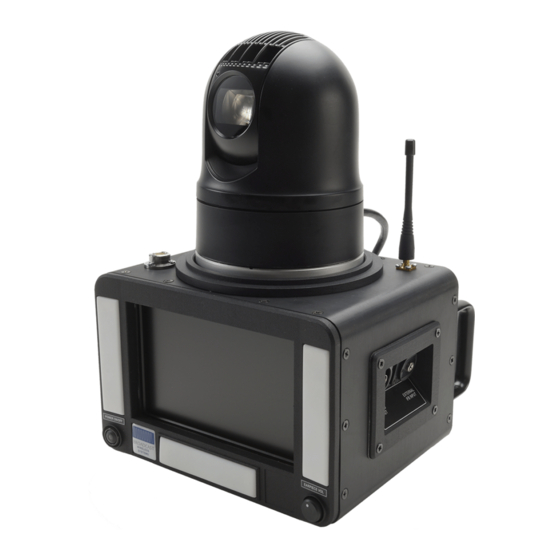
BROADCAST SoloCAM User Manual WIRELESS SYSTEMS Introduction to the SoloCAM Totally self-contained, portable indoor/outdoor live contribution system supplied in a lightweight Pelicase with tripod and space for a 3G/4G bonding unit. There are three versions of SoloCAM: SoloCAM Lite Basic system designed for self-operation by the reporter or on-site producer via infra-red remote control ▪... -
Page 9: Safe Operating Procedures
BROADCAST SoloCAM User Manual WIRELESS SYSTEMS Safe Operating Procedures • Operate within the environmental limits specified for the product. • Only authorized, trained personnel should open the product. There are no functions that require the User to gain access to the interior of the product. -
Page 10: Unpacking The Solocam
BROADCAST SoloCAM User Manual WIRELESS SYSTEMS Unpacking the SoloCAM The SoloCAM is supplied in lightweight Peli 1604 Air case with custom foam insert. This case should be used to transport the SoloCAM if it is necessary to return the unit to BWS. -
Page 11: Setting Up The Tripod
BROADCAST SoloCAM User Manual WIRELESS SYSTEMS Setting up the Tripod Set the tripod head to the horizontal position by turning the level locking knob anti-clockwise Extend the head support by twisting the locking ring anti-clockwise and pulling the head upwards... - Page 12 BROADCAST SoloCAM User Manual WIRELESS SYSTEMS Extend the tripod legs by releasing the clips for each section – set to the desired height Push down the lock and rotate the locking mechanism anti-clockwise...
- Page 13 BROADCAST SoloCAM User Manual WIRELESS SYSTEMS Drop the SoloCAM into the tripod head and release the locks – it should click into place. Point the unit at the subject and adjust the level mechanism so that the bubble is in the...
-
Page 14: Connections
BROADCAST SoloCAM User Manual WIRELESS SYSTEMS Connections Rear Panel 1. DC Output – 12VDC utility power outlet (for 3G/4G bonding device, COFDM TX etc) 2. Streaming Output + IP Control & Monitoring (SoloCAM Stream only) IP streaming output with SRT (up to 30Mbps) -
Page 15: Left Side Panel (Contributor)
BROADCAST SoloCAM User Manual WIRELESS SYSTEMS 5. Monitor External Input – Switchable HDMI external input to monitor (for AutoCue etc) 6. DMX Lighting Control – used to control external lighting rigs with DMX control interface 7. SIM Card Holder (SoloCAM Plus SoloCAM Stream) – SIM card for GPRS remote control and dial-up IFB 8. -
Page 16: Right Side Panel (Tx)
BROADCAST SoloCAM User Manual WIRELESS SYSTEMS Right Side Panel (TX) 12. Video Out – HD-SDI output with embedded audio (for connection to the TX device) 13. IFB Input – External IFB input (automatically disconnects the internal dial-up IFB) -
Page 17: Remote
BROADCAST SoloCAM User Manual WIRELESS SYSTEMS 14. Level Indicator – the bubble should be inside the inner circle 15. GPRS/Cellphone Antenna – receives GPRS remote control data and incoming IFB cellphone calls 16. ‘Soft’ Lighting – indoor lighting (‘tungsten’ colour temperature 3000K) 17. -
Page 18: Local Operation
BROADCAST SoloCAM User Manual WIRELESS SYSTEMS Local Operation The basic mode of operation is local control by the reporter/contributor or on-site production person using the IR remote control. Video from the unit is fed via a BNC cable to a transmission device such as a 3G/4G bonding unit, transmission truck or plug-in video point. -
Page 19: Setting The Shot
BROADCAST SoloCAM User Manual WIRELESS SYSTEMS Setting the Shot Where possible, position the SoloCAM so that any ambient light is shining on the contributor’s face, rather than into the lens of the camera. With contributor in place, set the shot using the PAN and ZOOM controls on the remote control. -
Page 20: Remote Operation (Plus And Stream Versions Only)
BROADCAST SoloCAM User Manual WIRELESS SYSTEMS Remote Operation (PLUS and STREAM versions only) These versions are fitted with a cellphone modem which allows remote control of all functions by the studio. It will also automatically receive incoming calls and route them to the IFB EARPIECE OUTPUT. -
Page 21: Logging On To The Control Server
BROADCAST SoloCAM User Manual WIRELESS SYSTEMS The SIM is inserted with the contacts facing downwards into the metal cage on top of the green PCB area. Don’t forget to replace cover as this helps to keep the SIM card in place. - Page 22 BROADCAST SoloCAM User Manual WIRELESS SYSTEMS A list of all the SoloCAMs in your network will be displayed. If they are active ie: logged onto the server, they will have a green background. Inactive units will have a red background.
-
Page 23: Camera Controls
BROADCAST SoloCAM User Manual WIRELESS SYSTEMS Please be patient! The controls operate with very little delay, but if a LiveU-type 3G/4G bonding device is being used to transmit the video, there may be up to a 2 second lag on the link, meaning any control inputs will not be seen in the studio during the lag period. -
Page 24: Lighting Control
BROADCAST SoloCAM User Manual WIRELESS SYSTEMS Lighting Control The SoloCAM has a flexible platform of built-in and remote lighting to cater for most deployment situations: Headlight – this is a daytime (~6000K colour temperature) light, mounted on top of the camera and is primarily used for lighting the contributors face in the presence of bright backgrounds. - Page 25 BROADCAST SoloCAM User Manual WIRELESS SYSTEMS If necessary, the camera can be removed from the base and mounted remotely. If the camera is mounted up-side down the image will automatically re-orientate itself. A remote power/control extension cable can be purchased from BWS if required.
-
Page 26: Ip Streaming Operation (Stream Version Only)
BROADCAST SoloCAM User Manual WIRELESS SYSTEMS IP Streaming Operation (STREAM version only) The STREAM version of SoloCAM has a built-in BWS Sapphire HEVC encoder capable of streaming video at up to 30Mbps with SRT. The SoloCAM is shipped in DHCP mode. To find... -
Page 27: Encoder Gui
BROADCAST SoloCAM User Manual WIRELESS SYSTEMS Encoder GUI The Sapphire Encoder Status page will initially load: The Sapphire HEVC Encoder is a high specification unit capable of up to 4K 10-bit 4:2:2 operation. As SoloCAM only operates in standard HD, many of the parameters are not required and one or two settings are unique, due to the internal architecture of the SoloCAM. - Page 28 BROADCAST SoloCAM User Manual WIRELESS SYSTEMS On the Audio tab, please leave the following parameters unchanged:...
-
Page 29: Bws Rebro Server
BROADCAST SoloCAM User Manual WIRELESS SYSTEMS The streaming settings are in the IP tab: The unit will stream using UDP, RTP or SRT protocols and it is assumed the user is familiar with the settings associated with these modes. If you do require further help or advice, please contact BWS on +44-1489-505034 or email support@broadcastwirelesssystems.com... -
Page 30: Technical Specifications
BROADCAST SoloCAM User Manual WIRELESS SYSTEMS Technical Specifications Connectors Microphone In XLR 3 pin Female Ext IFB In 3.5mm Jack Socket HDSDI Out XLR BNC Female HDMI In XLR HDMI XLR3 pin Female Network XLR RJ45 IFB Out XLR3 pin Male... -
Page 31: Connector Information
BROADCAST SoloCAM User Manual WIRELESS SYSTEMS Connector Information Rear Connector Panel 12VDC OUT – XLR4 Female Pin No. Signal 12VDC NETWORK/STREAMING – RJ45 Female CAMERA VIDEO I/P – BNC Female CAMERA PWR/CTRL – XLR4 Female Pin No. Signal CTL Data +... -
Page 32: Lh Connector Panel
BROADCAST SoloCAM User Manual WIRELESS SYSTEMS LH Connector Panel IFB EARPIECE OUT – XLR3 Male Pin No. Signal Screen Signal+ Signal- MIC INPUT – XLR3 Female Pin No. Signal Screen Signal+ Signal- RH Connector Panel VIDEO OUT – BNC Female EXTERNAL IFB INPUT –...
Need help?
Do you have a question about the SoloCAM Series and is the answer not in the manual?
Questions and answers