Table of Contents
Advertisement
Quick Links
Advertisement
Table of Contents

Summary of Contents for Quest Engineering TELSEC MP2
- Page 1 TELSEC® MP2 User Guide Rev 1.1 05/08/19...
- Page 2 CRITICAL APPLICATIONS DISCLAIMER QUEST PRODUCTS ARE NOT INTENDED OR AUTHORIZED FOR USE IN ANY APPLICATION THAT REQUIRES FAIL-SAFE OPERATION, OR ANY SYSTEM THAT IS RESPONSIBLE FOR PROVIDING DETECTION, MONITORING OR CONTROL OF CRITICAL SAFETY, LIFESAVING OR LIFE-SUPPORT CONDITIONS, FUNCTIONS OR OPERATIONS (INCLUDING BUT NOT LIMITED TO FIRE DETECTION, ALARMING, OR SUPPRESSION), OR ANY APPLICATION WHEREIN A FAILURE OR MALFUNCTION OF THE PRODUCT MAY LEAD TO SEVERE PROPERTY OR ENVIRONMENTAL DAMAGE, PERSONAL INJURY OR DEATH.
- Page 3 Revision History Date Rev # Modifications 4/5/19 Initial release K. Nickel 5/8/19 Added FCC statement K. Nickel Rev 1.1 05/08/19...
-
Page 4: Table Of Contents
Table of Contents Overview ............................... 1 Getting Started ..........................1 Product Specifications ........................... 2 Installation ............................3 Mounting the MP2 ........................3 Powering and Grounding ......................3 Connecting the Ethernet ....................... 4 Wiring inputs ..........................4 Wiring for Modbus ........................6 Line Termination ........................... - Page 5 Alarm Dispatch Settings ......................25 Bypass Outputs ........................... 27 User Administration ........................27 Advanced Settings ........................27 Programming the System ........................31 Input Programming ........................31 Output Programming ........................33 Modbus Programming ........................ 35 Alarm Programming ........................39 Time Schedules ........................... 45 Troubleshooting ..........................
-
Page 6: Overview
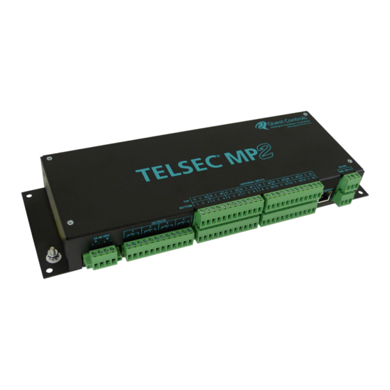
1 Overview ® The TELSEC MP2 is designed to provide advanced monitoring and alarming for remote facilities and cabinets using industry standard communications protocols such as SNMP, DNP3 and SMTP (Email) over Ethernet. The system has a built-in web server for status review and programming and can be polled using SNMP GET requests. -
Page 7: Product Specifications
2 Product Specifications Specifications Part number: 151052-32 ▪ Inputs: 32 universal inputs supporting 0-5 VDC, 4-20 mA, thermistor & contact closure ▪ Outputs: 4 form C digital outputs. Contact rating: 0.5 A @ 60 VDC ▪ Network interface: Ethernet 10/100 Base-T ▪... -
Page 8: Installation
3 Installation All local and national electrical safety codes (NESC®) must be followed when installing the MP2. If there is any contradiction in this manual and those standards, then the installer must follow the local and ® national codes. Use copper conductors only. The TELSEC MP2 is designed for mounting on a wall or within a rack. -
Page 9: Connecting The Ethernet
3.2.3 Grounding the MP2 There is a ground post on the left and right side of the chassis. Place a ground wire using a minimum 12 AWG conductor from the Electrical panel ground bus (or other approved grounding point) to the ground terminal on the MP2. - Page 10 Sensor Output 24 VDC Power supply TEMP Common Ground Reference Sensor Power Figure 3 - Wiring Voltage Sensors 3.4.3 Current Sensors ® The TELSEC MP2 can read and scale any linear current input from 0 to 20 mA. An external 249-ohm resistor (recommend 1% tolerance) is required to convert the signal to voltage and will require an external voltage source to power the sensor.
-
Page 11: Wiring For Modbus
the sensing voltage. The detection point for determining ON/OFF status is greater than 2.8 VDC and less than 0.8 VDC. There is no transition when the voltage is between these two values. Both wet and dry input types are connected between the input terminal and a common terminal. For Wet inputs the voltage must be between 0VDC and up to +65VDC. -
Page 12: Line Termination
8. At the MP2, connect the cable shield to the protective (protected) earth ground. The cable shields must not be connected to earth ground anywhere else in the cabling network except at this point. 3.6 Line Termination 1. At each end of the Modbus cable network daisy-chain, there must be an end of line termination resistor. - Page 13 ® Drawing A - shows the TELSEC MP2 in the center of the chain © TELSEC Switch 2 up Drawing B - shows the MP2 on the end of the chain. © TELSEC Switch 2 down Figure 7 - Typical Modbus Networks ©...
-
Page 14: Wiring Outputs
3.8 Wiring Outputs There are four form C relays available for control of external devices based upon alarm conditions or time schedules. Place wire between the common and normally open or normally closed terminals for each output on the MP2. The relays are designed for Class 2 wiring and are rated for a maximum of 1 amp at 24VAC or 30VDC, 0.3 A @ 60VDC. -
Page 15: Restoring To Factory Defaults
associated to an alarm severity will be “active” when the alarms are present and will deactivate when either all alarms with the associated severity have cleared or if the acknowledge function is used. Outputs associated with a time schedule will be “active” when the schedule is on and de- activated when the schedule is off. -
Page 16: Web
5.2 Web Page Navigation All MP2 web pages will have a top header section that shows the Site Name, the systems date and time, Alarm bell icon and a menu ribbon with the available choices for navigation. The choices presented on the menu ribbon will be dependent on the access level of the password used. -
Page 17: Input Status
6.1 Input Status The input status page will show the current value of the universal inputs currently programmed in the system. The status page groups the inputs based on their definition, into either digital inputs or analog inputs. The display will show the digital inputs first followed by the analog points. Click on the expand window icon to display the points. -
Page 18: Modbus Status
6.1.2 Analog Inputs Analog input status will show the input number, the programmed name for the point and the current value of the input in the defined engineering units. The related alarms column will indicate the number of active alarms currently present that reference the input. A number greater than 0 will be a hyperlink that will bring up a window showing a table of active alarms for the point. -
Page 19: Output Status
Figure 14 - Modus Input Status Modbus points that are writable, will be displayed with a write icon . Clicking on this icon will bring up a window to allow the user to change the value. Enter the value in the converted engineering units that are being displayed. -
Page 20: Log Data
6.4 Log Data The MP2 will plot a graph of up to four points at a time. The page controls will allow the user to select from Analog Inputs, Digital Inputs Modbus and Digital Outputs. Any combination of point types can be charted at one time. -
Page 21: Alarms
7 Alarms Hovering on the Alarms menu will provide the choices of Alarm Status, Active Alarm Log and Historical Alarm log. 7.1 Alarm Status The Alarm Status page will provide the current status of all the defined alarm points. Each alarm point will be listed with the defined name, the name of the point being referenced in the alarm, a timestamp when the alarm point last transitioned to its current value and the current value of the point. -
Page 22: Historical Alarm Log
Figure 19 - Active Alarms Page 7.3 Historical Alarm Log The Historical Alarm page will show the alarm history of the stored alarms. Use the back, next, beginning and ending button on the bottom of the table to navigate through the list of alarms. The Download To CSV button will create a CSV file and download it to your computer. -
Page 23: Configuring The Mp2
7.3.1 Filtering Alarm Data Use the TYPE/DATE FILTER functions to filter the alarm severity and the Start/Stop Date fields to select the specific desired ranges. The page has additional filters for the alarm category (All, Inputs, Modbus by device) and the ability to word match the name of the alarm and/or the data point being referenced in the alarm. -
Page 24: System Setup
8.1 System Setup Select Settings from the main menu and choose General. The MP2 will display a list of options for configuration with the first one being Site Parameters. Click on each accordion header to modify the settings for each section and press Save Settings to write the changes to non-volatile flash memory. Save Settings will cause the system to save the changes and reboot to come up with the new values. - Page 25 Figure 23 - Site Name and Information 8.1.2 IPV4 Configuration The MP2 supports dual stack for IPv4 and IPv6 or you can disable either IPv4 or IPv6. The default setting is for IPv4 to be enabled and IPv6 disabled. The system will not allow a user to disable both. Use this section to enable/disable IPV4 protocol and to configure an IP address for the unit.
- Page 26 Figure 25 - IPv6 settings 8.1.4 IP General This section is used to enter the DNS server IP addresses, change the default IP port, enable/disable SSL and configure the location of where the update server is located. When selecting SSL, the system will allow you to copy/paste the contents of your own PEM data file if you have one.
- Page 27 Figure 27 - System clock settings 8.1.6 Serial Ports The MP2 has two RS485 serial ports that can be used for Modbus RTU or DNP3. The Modbus option makes the MP2 a Modbus master to poll equipment that support Modbus RTU protocol. The DNP option will allow the MP2 to function as a DNP outstation to provide status of its universal inputs and digital outputs.
- Page 28 8.1.7 DNP Configuration The MP2 supports DNP3 via ethernet and serial communications. The DNP option will allow the MP2 to function as a DNP outstation to provide status of its universal inputs and digital outputs. The system supports polling of the points along with unsolicited messages of inputs defined as digital and digital outputs.
- Page 29 Figure 30 - SNMP and Email configuration 8.1.9 SNMPv3 User Configuration Use this section to create up to four different users for SNMP Set/Get access to the system and sending traps if v3 traps are configured under the Settings/Dispatch page. The MP2 supports authentication using MD5 or SHA and Privacy using DES or AES.
-
Page 30: Alarm Dispatch Settings
the RADIUS server. See Appendix B - RADIUS Server Configuration for the required setting when configuring the RADIUS server. Figure 32 - RADUIS server interface setup 8.2 Alarm Dispatch Settings The Alarms Dispatch option under the Settings menu will display the current settings for both the SNMP dispatch and Email dispatching of alarms. - Page 31 8.2.2 Email Dispatch Click on the Email Dispatch expand icon to display the settings for creating email distribution. The Email server settings must be configured in order for emails alarming to occur (See section 8.1.8). The MP2 supports nine email addresses for sending alarms. Enter the users email address or distribution list address to be used.
-
Page 32: Bypass Outputs
8.3 Bypass Outputs The bypass output page is used to turn on (activate) or off (deactivate) the outputs. Select a time duration from the dropdown or the word FOREVER and then select the desired action of ON or OFF. Outputs bypassed for a time period will return to automatic mode once the time elapses. Outputs bypassed FOREVER must be manually returned to automatic by selecting Auto. - Page 33 8.1.4. Alternatively, the MP2 can be upgraded locally using an SD card. Contact Quest for upgrade information. Figure 37 - Firmware version and update 8.5.2 Configuration Upload & Download Select the expand arrow to display the option for downloading or uploading a configuration file to the system.
- Page 34 Figure 38 - Configuration file upload & download 8.5.3 Point Log Removal This section will allow clearing of log data for a single point or erasing history log data for all the points. It is not necessary to remove periodically remove log data since the system will overwrite old data when the log is full.
- Page 35 Figure 40 - Clear input timers 8.5.5 Event & Debug Log The Event and Debug log will provide diagnostic information regarding the operation of the MP2. Typical use of this log would be to resolve issues with sending traps or email alarms. Contact Quest for assistance if you are experiencing issues with your MP2 system.
-
Page 36: Programming The System
9 Programming the System Hovering on the Program menu will display the available program options. For all program pages the system must save changes/additions to flash and do a reboot. When entering data, you will notice that after pressing the Done button there will be a 60 second count down timer in the header. You will have 60 seconds to enter the next point information, which will reset the timer to 60 seconds again. - Page 37 Figure 43 - Add/change input settings 9.1.1 Point This is the physical location of the input on the back of the MP2. Use the dropdown to select input 1-32. 9.1.2 Point Name The point name will allow up to thirty-two characters to describe the point being monitored. The name is case sensitive and will be displayed exactly as you typed it.
-
Page 38: Output Programming
9.1.4 Offset The offset field is used for any analog sensor to correct the reading of the input. The MP2 will read the input and add the offset value automatically so all alarms, logging and display screens show the corrected value. 9.1.5 Custom Low This field is used when selecting the CUSTOM input type and will be the value displayed when the input... - Page 39 9.2.2 Default State The default state is the condition of the relay when it is not being commanded to the active state. This option allows for the relay coil to be either de-energized or energized as the default state of the relay. Select whether the output should be De-energized when not activated (normal relay logic) or Energized when not in the activated state (reverse relay logic).
-
Page 40: Modbus Programming
Figure 46 - Adding an Acknowledge input Press the Done button to go back to the program outputs page and then select another output to program or press the Save Settings button. 9.3 Modbus Programming The Modus programming option will be present if either serial port 1 or 2 is defined for Modbus. Both ports can be configured simultaneously to provide a total of 1024 Modbus points (2 ports x 512 registers each). - Page 41 Figure 48 - Modbus define device page 9.3.2 Modbus Registers Click on the expand window icon for the device that you want to add registers. The window will show the defined registers with navigation buttons for forward, back, beginning and end along with a link to add new points.
- Page 42 Figure 50 - Defining Modbus registers 9.3.3.1 Modbus ID The ID field is a unique alphanumeric four-character code used to identify the point in the system. This is used for alarm programming, and SNMP to create a reference ID for the point. The four-character ID can be whatever the user would like to use to organize the points.
- Page 43 means the lowest bit and 16 means the highest bit. Some register map will show 0-15 and in that case 0 is the first bit and 15 is the 16 bit. 9.3.3.6 Register Format Use the Format drop down to select the register type. Digital inputs and Coil registers are single Byte format.
-
Page 44: Alarm Programming
9.4 Alarm Programming Select Alarms from the Program menu to see the alarm program screen. This screen will display all programmed alarms in a table with the ability to navigate the table using the next, back, beginning and end buttons. In addition, the page has filter options to display all alarm points or just those associated with the direct inputs or Modbus ports. - Page 45 9.4.1 Defining Alarm Strategies Selecting an existing alarm name or clicking on the Add new alarm button will bring up the dialog for modifying or adding a new alarm. Figure 53 - Defining an alarm strategy 9.4.1.1 Alarm ID The ID field is a unique alphanumeric four-character code used to identify the point in the system. This is used for alarm programming, and SNMP to create a reference ID for the point.
- Page 46 for a list of defined Modbus points sorted by device. Select the desired category and then select the Device ID to be used for the alarm strategy. Figure 54 - Selecting a point to alarm 9.4.1.4 Alarm Severity Select the desired alarm severity from the Severity dropdown. A severity of NONE will disable the alarm until the severity is changed to another level.
- Page 47 Figure 55 - Selecting the alarm severity 9.4.1.5 Comparison operator and value The Comparison field is used to select the operator for creating the alarm strategy. The alarms are looking for “true” statements and will alarm when the condition described is in the true state. The value field is used with the operator to determine if the point being monitored is in the alarm condition.
- Page 48 Figure 56 - Select comparison operator 9.4.1.6 Additional Qualifier Alarm strategies allow for a qualifier to create additional conditions that must be true (on) before this alarm statement is true or active. The qualifier field is optional and will contain a list of previously defined alarm strategies and time schedules.
- Page 49 Figure 57 - Using additional qualifiers 9.4.1.7 Alarm Delay and Delay Units Use the Alarm Delay field and the Delay Units drop down to create a delay time for the alarm condition. The alarm condition must be true for this time period for the alarm to be generated. An alarm will not be generated if the conditions become false before the delay time elapses.
-
Page 50: Time Schedules
9.5 Time Schedules Select Schedule from the Program menu to see the Program Schedule page. This page will show the defined schedules and their current status or state. The name of the schedule is a hyperlink that when selected will bring up a window showing the current settings and allow the user to modify the schedule. The “Add new schedule”... - Page 51 Figure 59 - Define schedule priorities © Rev 1. 1 05/08/19 - 46 - TELSEC MP2 User Guide...
-
Page 52: Troubleshooting
10 Troubleshooting The following section is designed to help you isolate the most likely system malfunctions that may occur. For additional help, contact Quest’s Technical Support and Service Center. 10.1 Power Up PROBLEM ▪ Green Power Light is not blinking every second. SOLUTION 1) Use a volt meter and verify that the incoming power to the MP2 is between 18 and 65VDC. -
Page 53: Alarm Notification Failure
® 2) Verify the relay on the TELSEC MP2 opens and closes when using the bypass command from the web server or via SNMP set to the output 3) Verify the wiring to the control point is correct 4) Verify the control source voltage (typically an external 24 VAC transformer) is operable and supplying proper voltage. -
Page 54: Appendix A - Snmp Trap Format
4) Verify the proper wiring between the MP2 and all slave devices. Isolate the bus to one device first to see if you can get data from that device and then move on to the next device in the chain. Appendix A - SNMP Trap Format ®... -
Page 55: Appendix B - Radius Server Configuration
notifySiteId 11476.100.1.9 Text String The programmed site identification value for the system. notifyPointOID 11476.100.1.10 Object The OID of the value of the point in alarm Identifier Appendix B - RADIUS Server Configuration For the RADIUS server configuration, you must use the “Filter-ID” attribute for each user to have access. Inside the “Filter-ID”... -
Page 56: Appendix C - Sd Card Update
Appendix C – SD Card Update Overview ® The TELSEC MP2 can be upgraded using a standard SD memory card. The system supports firmware upgrade as well as loading application programs with an SD card. Use this procedure when you need change or upgrade the application program of your system. -
Page 57: Appendix D - Email Alarm Format
Appendix D – Email Alarm Format ® The TELSEC MP2 will generate text-based emails for alarm conditions. The email notification will follow a specific format which is outlined below. Format: Subject line: MP2 <email type> (<severity>) - <user defined subject line> Email body: MP2 named <site name>... -
Page 58: Contact Information
Contact Information Website: www.questcontrols.com Email: General information: info@questcontrols.com Technical support: CustomerService@questcontrols.com Mailing Address: Quest Controls, Inc. 208 9th Street Dr. West, Palmetto FL 34221 Key Phone Numbers Main Number: (941) 729-4799 Fax: (941) 729-5480 Place Orders or Check Scheduling & Delivery: (941) 729-4799, option 3 Technical &...
Need help?
Do you have a question about the TELSEC MP2 and is the answer not in the manual?
Questions and answers