Table of Contents
Advertisement
Quick Links
Owner's Manual
Owner's Manual
Parts Manual
Parts Manual
READ THIS MANUAL CAREFULLY,
IT CONTAINS IMPORTANT SAFETY INFORMATION.
GT200IIR
MINIMUM
RECOMMENDED
OPERATOR AGE:
FOR OFF-ROAD USE ONLY
This vehicle is designed and manufactured for off-road use only.
USA only:
It does not conform to Federal Motor Vehicle Safety Standards, and in regards
to operation on public streets, roads, or highways is illegal.
16
Hammerhead
Advertisement
Table of Contents

Related Manuals for Twister GT200IIR

Summary of Contents for Twister GT200IIR
- Page 1 Owner's Manual Owner's Manual Hammerhead Parts Manual Parts Manual READ THIS MANUAL CAREFULLY, IT CONTAINS IMPORTANT SAFETY INFORMATION. GT200IIR MINIMUM RECOMMENDED OPERATOR AGE: FOR OFF-ROAD USE ONLY This vehicle is designed and manufactured for off-road use only. USA only: It does not conform to Federal Motor Vehicle Safety Standards, and in regards...
- Page 2 This warranty does not apply to any part, which in opinion of seller was defective because of improper maintenance, improper assembly, alterations,abuse, negligence or accident. Should warranty service be required on your GT200IIR during the 90 days warranty period, please contact your nearest authorized dealer for repairs.
-
Page 3: Table Of Contents
CONTENTS OWNER' S MANUAL Page 1. FOREWORD ------------------------------------------------------------------------------------------------------------------------- 2. A FEW WORDS ABOUT SAFETY -------------------------------------------------------------------------------------------------- 3. IMPORTANT SAFETY INFORMATION -------------------------------------------------------------------------------------------- 4. STEERING ADJUSTMENT------------------------------------------------------------------------------------------------------------ 5. SAFETYLABELS---------------------------------------------------------------------------------------------------------------------- 6. ARE YOU READY TO DRIVE ? ----------------------------------------------------------------------------------------------------- 6. SAFE DRIVING PRECAUTIONS ---------------------------------------------------------------------------------------------------- 7. P.D.L---------------------------------------------------------------------------------------------------------------------------------- 8. -
Page 4: Foreword
FOREWORD Thank you for purchasing our Kart. We hope you will enjoy it. Before you start to operate the Kart, please read through this Owner's Manual carefully as it contains important safety and maintenance information. Failure to follow the warnings contained in this manual can result in serious injuries or death. Be sure to follow the recommended maintenance schedule and service your kart accordingly. -
Page 5: A Few Words About Safety
A FEW WORDS ABOUT SAFETY In order to keep everyone safe, you must take responsibility for the safe operation of your Kart. To help you make informed decisions about safety, we have provided operating procedures and other information on labels and in this manual. This information alerts you to potential hazards that could hurt you or others. -
Page 6: Important Safety Information
IMPORTANT SAFETY INFORMATION Your Kart will provide you with many years of service and pleasure.Providing you take responsibility for your own safety and understand the challenges you can meet while driving. There is much that you can do to protect yourself while operating your kart. You'll find many helpful recommendations throughout this manual. - Page 7 IMPORTANT SAFETY INFORMATION Drive within Your Limits Pushing limits is another major cause of Kart accidents. Never drive beyond your personal abilities or faster than conditions warrant. Remember that alcohol, drugs, fatigue, and ina�ention can significantly reduce your ability to make good judgments and drive safely.
-
Page 8: Steering Adjustment
STEERING ADJUSTMENT Steering adjustment Your kart comes with tilt steering.To adjust, you should unscrew the adjusting knob marked A, unscrew out till the arm can move up and down. Pick the best spot for your comfort and retighten the adjusting knob. WARNING Before attempting to run your kart, make sure the adjusting knob has been tighten. -
Page 9: Safetylabels
SAFETY LABELS This section presents some of the most important information and recommendations to help you drive your Kart safely. Please take a few moments to read these pages. The labels should be considered permanent parts of the Kart. If a label comes off or becomes hard to read, contact your dealer for warning label replacements. -
Page 10: Are You Ready To Drive
ARE YOU READY TO DRIVE ? Before each drive, you need to make sure that you and your kart are both ready to drive. To help get you prepared, this section discusses how to evaluate your driving readiness, what items you should check on your kart, and adjustments to make for your comfort, convenience, or safety. - Page 15 ...
- Page 17 SPEEDOMETER IGNITION START SWITCH REVERSE LEVER THROTTLE PEDAL BRAKE PEDAL PARKING BRAKE...
-
Page 19: Operation
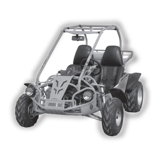
OPERATION Component locations STEERING WHEEL SEAT BELT REAR CARGO RACK TANK COMP. FUEL FUEL TANK CAP Figure 2... - Page 20 OPERATION C. Passengers The vehicle allows for two riders only. Combine maximum weight of driver and the passenger should not exceed 180kg or 400lbs. D. Seat Adjustment The seat must always be securely fastened in the position which best affords the operator control of the foot pedals, steering wheel, and the remote stop bu�on.
-
Page 21: Operation/Service Instructions
OPERATION/SERVICE INSTRUCTIONS F. Starting And Operating Instructions a. Before starting the engine, be sure that the driver is seated properly in the Kart with the seat belt. b. Testing the Kart in an open space at the beginning to learn how to start, turn and stop. c. - Page 22 SERVICE INSTRUCTIONS B. Engine Lubrication You must change the oil in the crankcase a�er the first 5 hours of operating of your new engine (See Fig. 7) and a�er 10 hours of use therea�er. That will insure proper lubrication of internal parts and prevent costly repairs due to excessive wear.
- Page 23 SERVICE INSTRUCTIONS a. Warm up the engine (5~10min) b. Tighten the air screw gently. Backout 2-3/8 turns counter clockwise. c. Connect the tachometer, adjust the thro�le to limit the idle speed. The standard value is (1400RPM). d. Turn the air screw counter clockwise slowly and observe the RPM of the engine, stop adjusting as the RPM reaches the top speed.
- Page 24 SERVICE INSTRUCTIONS H. Chain Adjustment Check the chain adjustment a�er first two hours of use. Readjust if it has more than 1/2” flex. a. Loosen Nut #1 b. Adjust Nut #2. Turn Nut #2 clockwise in 1/2 turn increments, then turn nut #1 until tight. Follow this procedure until chain is at proper tension (See Fig.
-
Page 25: Repair
REPAIR A. Front Wheel Replacement Do not disassemble the castle nuts when you replace the front wheels. It is only necessary to remove the 4 lug nuts to remove the wheel. (See Fig. 12) Tighten the nuts a�er replacing the wheels. Figure 12 B. - Page 26 REPAIR C. Front Wheel Alignment a. The front wheels should be “toe-in” from 1/8” to 1/4”. To check for alignment, measure distance A and B between the centerline (CL) of the wheels. The proper toe-in dimension A should be 1/8” – 1/4” greater than dimension B. b.
-
Page 27: Periodical Check And Services
PERIODICAL CHECK AND SERVICES The maintenance intervals in the following table are based upon average driving conditions. Driving in unusually dusty areas, require more frequent servicing. Time of service Initial service Monthly Quarterly Yearly Items (first week) Tire pressure/wear Brake performance Tightness of screws Air cleaner Carburetor... - Page 28 FIG.1 CYLINDER HEAD ASSY.
-
Page 29: Parts Manual
PARTS MANUAL CYLINDER HEAD ASSY. REF NO. PART NO. DESCRIPTION REGD NO. M200-0101 CYLINDER HEAD SUBASSY 98056-57713-00 SPARK PLUG (C7HSA NGK) M150-1001010 CYLINDER HEAD GASKET M150-1001004 CARBURETOR INSULATOR GASKET M150-1001005 CARBURETOR INSULATOR M150-1001210 PIPE COMP. IN M150-1001220 INSULATOR BAND M150-1001103 HEAD COVER GASKET M150-1001201 O-RING 27X2... -
Page 30: Cylinder Assy
FIG.2 PARTS MANUAL CYLINDER ASSY. CYLINDER ASSY. REF NO. PART NO. DESCRIPTION REGD NO. M150-1002200 CYLINDER COMP. M150-1002001 CYLINDER GASKET 90442-06000-KAT WASHER SEALING 6 M150-1001007 DOWEL PIN 10X16 96001-06012-KAT FLANGE BOLT M6X12-ZN. D M150-1002002 GASKET TENSIONER LIFTER M150-1002100 TENSIONER LIFTER ASSY. 96001-06020-KAT FLANGE BOLT 6X20... - Page 31 FIG.3 PARTS MANUAL CRANKCASE ASSY. (1) CRANKCASE ASSY.(1) REF NO. PART NO. DESCRIPTION REGD NO. M150-1003101-B R CRANKCASE COVER COMP. M150-1003013 CRANKCASE COVER GASKET M150-1003104 CAP TAPPET ADJUSTING HOLE M150-1003120 OIL FILTING SCREEN M150-1003102 OIL FILTING SCREEN SPRING M150-1003105 OIL LEVEL GAUGE M150-1003006 AC GENERATOR CORD CLAMPER M150-1003110...
-
Page 32: Crankcase Assy.(1)
FIG.4 PARTS MANUAL CRANKCASE ASSY. - Page 33 PARTS MANUAL CRANKCASE ASSY. REF NO. PART NO. DESCRIPTION REGD NO. M200-0401 CRANKCASE ASSY. R. M150-1003320 FRONT HANGER BUSHING M150-1003014 CRANKCASE GASKET M200-0404 CRANKCASE ASSY. L. M200-0405 REVERSE CABLE FIX PLATE M200-0406 CRANKCASE SEAL M200-0407 WASHERΦ8 M200-0408 BOLT M8×12 M200-0409 WASHER Φ12 M200-0410 DRAIN PLUG BOLT M12...
-
Page 34: Crankshaft Con'rod &Piston Assy
FIG.5 PARTS MANUAL CRANKSHAFT CON'ROD & PISTON ASSY. CRANKSHAFT CON'ROD & PISTON ASSY. REF NO. PART NO. DESCRIPTION REGD NO. M200-0501 CRANKSHAFT & CONROD ASSY. M150-1004007 NUT M12X1.25 M150-1004011 WASHER 12-149HV 12-140HV M150-1004009 LOCKING NUT M150-1004013 WASHER M200-0506 KICK DRIVE GEAR M150-1040005 WASHER Φ12... -
Page 35: Camshaft Assy
FIG.6 PARTS MANUAL CAMSHAFT ASSY. CAMSHAFT ASSY. REF NO. PART NO. DESCRIPTION REGD NO. M150-1005004 TAPPET ADJUSTING NUT M150-1005003 TAPPET ADJUSTING SCREW M200-0603 VALVE ROCKER ARM M200-0604 EX ROCKER ARM SHAFT M200-0605 CAMSHAFT CHAIN M200-0606 CAMSHAFT COMP. 16T M200-0607 IN ROCK ARM SHAFT COMP. M200-0608 STOPPER PLATE COMP. -
Page 36: Left Crankcase Cover Assy
FIG.7 PARTS MANUAL LEFT CRANKCASE COVER ASSY. LEFT CRANKCASE COVER ASSY. REF NO. PART NO. DESCRIPTION REGD NO. M200-0701 LFFT CRAKCASE COVER M200-0702 LEFT COVER GASKET M200-0703 DOWEL PIN 8×12 M200-0704 HEX COLUMN M200-0705 STARTING MOTOR SEAL PIECE M200-0706 BUSHING M200-0707 BOLT M12×1.25 M200-0708... -
Page 37: Fan Cover And Shroud Assy
FIG.8 PARTS MANUAL FAN COVER AND SHROUD ASSY. FAN COVER AND SHROUD ASSY. REF NO. PART NO. DESCRIPTION REGD NO. FAN COVER COMP. M200-0801 STARTER CABLE CLAMPER M150-1009002 CARBURETOR COOLING DUCT M200-0803 M200-0804 LOWER SHROUD M200-0805 LOWER SHROUD SEAL M200-0806 UPPER SHROUD COMP. -
Page 38: Oil Pump Assy
FIG.9 PARTS MANUAL OIL PUMP ASSY. OIL PUMP ASSY. REF NO. PART NO. DESCRIPTION REGD NO. M150-1021000 CHAIN OIL PUMP M150-1020002 FLANGE NUT M6 M150-1020001 SPROCKET OIL PUMP DRIVEN M200-0904 BOLT M6X30 M200-0905 OIL PUMP SUBASSY. -
Page 39: Driven Pulley And Clutch Subassy
FIG.10 PARTS MANUAL DRIVE PULLEY AND CLUTCH SUBASSY. DRIVE PULLEY AND CLUTCH SUBASSY. REF NO. PART NO. DESCRIPTION REGD NO. M150-1032000 CLUTCH ASSY. OUTER M150-1033000 DRIVE BELT M150-1031000 DRIVE PULLEY ASSY. -
Page 40: Oil Cooler Assy.&Timing Chain Comp
FIG.11 OIL COOLER ASSY.&TIMING CHAIN COMP. OIL COOLER ASSY.&TIMING CHAIN COMP. REF NO. PART NO. DESCRIPTION REGD NO. OIL COOLER M200-1101 ALUMINUM WASHER M200-1102 OIL TUBE (1) M200-1103 OIL TUBE (2) M200-1104 HOLLOW BOLT M200-1105 CHAIN GUIDE PLATE M200-1106 CHAIN TENSIONER M200-1107 TENSIONER FIX BOLT M200-1108... -
Page 41: Electric System
FIG.12 PARTS MANUAL ELECTRIC SYSTEM ELECTRIC SYSTEM REF NO. PART NO. DESCRIPTION REGD NO. STATOR COMP. M150-1051200-8 FLYWHEEL COMP. M150-1051100 COOLING FAN COMP. M150-1051100-3 FLANGE BOLT M6x18 M150-1051100-4... -
Page 42: Electric Starter Assy
FIG.13 FIG.13 PARTS MANUAL ELECTRIC STARTER ASSY. ELECTRIC STARTER ASSY. REF NO. PART NO. DESCRIPTION REGD NO. FLANGE STARTING CLUTCH M150-1060001 STARTER REDUCTION GEAR SHAFT M150-1060002 M150-1060003 STARTER REDUCTION GEAR M150-1060004 FLANGE BOLT M6X16 M200-1305 STARTER MOTOR ASSY. -
Page 43: Drive Pulley Subassy
FIG.14 FIG.14 PARTS MANUAL PARTS MANUAL DRIVE PULLEY SUBASSY. DRIVE PULLEY SUBASSY. DRIVE PULLEY SUBASSY. DRIVE PULLEY SUBASSY. REF NO. REF NO. PART NO. PART NO. DESCRIPTION DESCRIPTION REGD NO. REGD NO. M150-1071000 MOVABLE DRIVE PULLEY ASSY. MOVABLE DRIVE PULLEY ASSY. M150-1071002 CLUTCH WEIGHTS... - Page 44 FIG.15 FIG.15 CARBURETOR CARBURETOR...
-
Page 45: Carburetor
PARTS MANUAL PARTS MANUAL CARBURETOR REF NO. REF NO. PART NO. PART NO. DESCRIPTION DESCRIPTION REGD NO. REGD NO. 16010-KAT-901 GASKET SET A JET NEEDLE SET 16012-KAT-903 16013-KAT-904 FLOAT SET 16015-KAT-905 FLOAT CHAMBER SET 16016-KAT-906 SCREW SET A 16028-KAT-907 SCREW SET B VALVE PLATE SET 16037-KAT-908 16046-KAT-909... -
Page 46: Reverse Gearbox Assy
FIG.16 PARTS MANUAL REVERSE GEARBOX ASSY. TRANSMISSION ASSY. REF NO. PART NO. DESCRIPTION REGD NO. M200-1601 GEARBOX COVER M200-1602 GEARBOX COVER GASKET M200-1603 BEARING 6202 M200-1604 THIRD SHAFT M200-1605 BEARING 6005 M200-1606 OIL SEAL 30×47×7 M200-1607 OUTPUT SHAFT M200-1608 FINAL GEAR M200-1609 SHAFT CIRCLIP 25 M200-1610... - Page 47 FIG.17 PARTS MANUAL SHIFT YOKE SHAFT COMP. SHIFT YOKE SHAFT COMP. REF NO. PART NO. DESCRIPTION REGD NO. M200-1701 LOCKING FLANGE NUT M200-1702 SHIFT YOKE HEAD M200-1703 WASHER M200-1704 CIRCLIP M200-1705 SHIFT YOKE M200-1706 SHIFT YOKE SHAFT M200-1707 SHAFT FIX BOLT M200-1708 FLAT WASHER 6 M200-1709...
-
Page 48: Frame Group
FIG.18 FIG.16 FRAME GROUP FRAME GROUP 32 31... - Page 49 PARTS MANUAL PARTS MANUAL FRAME GROUP FRAME GROUP REF NO. REF NO. PART NO. PART NO. DESCRIPTION DESCRIPTION REGD NO. REGD NO. 8.070.067 8.070.063 C.B.C. CROSS BAR C.B.C. REAR CROSS BAR 8.070.069 8.070.064 C.B.C. FRONT CROSS BAR MIDDLE C..C. CROSS BAR 8.070.065 8.070.065 C.B.C.
-
Page 50: Steering Shaft Assy
FIG.19 FIG.17 STEERING SHAFT ASSY. STEERING SHAFT ASSY. - Page 51 PARTS MANUAL PARTS MANUAL STEERING SHAFT ASSY. STEERING SHAFT ASSY. REF NO. REF NO. PART NO. PART NO. DESCRIPTION DESCRIPTION REGD NO. REGD NO. 7.010.041 7.010.041 STEERING BOLT COVER STEERING BOLT COVER 9.100.612 9.100.612 BOLT STRAP M6x12 BOLT STRAP M6x12 8.030.024 8.030.024 SPINDLE BRACKET...
-
Page 52: Suspension Arm Assy
FIG.20 FIG.18 SUSPENSION ARM ASSY. SUSPENSION ARM ASSY. - Page 53 PARTS MANUAL SUSPENSION ARM ASSY. REF NO. PART NO. DESCRIPTION REGD NO. 2.000.028 STRUT AND SPINDLE SUPPORT, R 9.108.105 FLANGE BOLT M8x1.25x105 8.010.015 UPPER SUSPENSION ARM COLLAR 7.010.003 UPPER SUSPENSION ARM BUSHING 4.000.004 UPPER SUSPENSION ARM 9.220.008 LOCKING FLANGE NUT. 7.010.140 LOCKING FLANGE NUT.
- Page 54 FIG.21...
- Page 55 REAR CARGO RACK 2.000.064 TUBE SEAT Φ25 7.010.017 RACK SUPPORT ARM 8.080.053 FLANGE BOLT M8x1.25x20 9.108.020 LOCKING FLANGE NUT. 9.220.008 FUEL TANK CAP COMP. 6.000.145 FUEL TANK COMP. 4.000.029 FLANGE BOLT M8x1.25x25 9.108.025 TANK COLLAR 8.010.034 RUBBER MOUNTING 7.020.005 FLAT WASHER Φ8 9.300.008 NYLON LOCKING FLANGE NUT...
- Page 56 FIG.22...
- Page 57 LOCKING FLANGE NUT 9.220.012 ENGINE MOUNTING LINK WASHER 8.010.042 ENGINE MOUNTING LINK CUSHION 7.020.001 ENGINE MOUNTING LINK SPACER 8.020.045 ENGINE MOUNTING LINK COLLAR 8.010.041 FLAT WASHER Φ12 9.300.012 9.200.012 ENGINE MOUNTING BOLT PLATE 6.000.026 LOCKING FLANGE NUT 9.220.010 FLANGE BOLT M6x22 9.106.022 LOCKING NYLON NUT...
- Page 58 FIG.23...
- Page 59 4.000.055 AIR CLEANER ASSY. 9.805.003 TAPPING SCREW M5X16 7.010.087 AIR CLEANER COVER 6.000.388 AIR CLEANER ELEMENT 7.010.088 AIR CLEANER CASE COMP 6.000.389 AIR CLEANER BREATHE TUBE 6.000.390 AIR CLEANER DUCT 8.020.228 AIR CLEANER CLAMP 9.040.016 EX.PIPE GASKET 6.000.024 CARBURETOR 2.000.065 ENGINE 150CC 6.000.393 SPRING...
- Page 60 FIG.24...
-
Page 61: Rear Swing Arm
PARTS MANUAL REAR SWING ARM REF NO. PART NO. DESCRIPTION REGD NO. FLANGE BOLT M10x1.25x40 9.110.040 LOCKING FLANGE NUT 9.220.010 6.000.006 CUSHION ASSY. RR 9.908.100 BOLT STRAP M8x1.25x100 6.000.101-GT REAR FENDER BRACKET, L LOCKING NYLON NUT 9.210.006 FLANGE BOLT M8x1.25x45 9.108.045 9.906.016 FLANGE BOLT... -
Page 62: Rear Housing
FIG.25 REAR HOUSING... - Page 63 PARTS MANUAL REAR HOUSING REF NO. PART NO. DESCRIPTION REGD NO. 9.108.022 FLANGE BOLT M8x1.25x22 8.010.053 BRAKE DISC. RR 9.220.008 LOCKING FLANGE NUT M8 8.010.231 REAR AXLE 7.060.040 DRIVE CHAIN 56’ 8.010.077 REAR SPROCKET 39TEETH 9.108.027 FLANGE BOLT M8x1.25x27 9.040.006 DUST SEAL 50X34-7 8.030.008...
-
Page 64: Wire Harness/Electrical
FIG.26 WIRE HARNESS/ELECTRICAL... - Page 65 PARTS MANUAL WIRE HARNESS/ELECTRICAL REF NO. PART NO. DESCRIPTION REGD NO. 7.010.093 SWITCH PANEL COVER 6.000.411 HEADLIGHT SWITCH 6.000.159 ENGINE STOP BUTTON 6.000.020-J IGNITION START SWITCH 6.000.395 WIRE HARNESS. 6.000.396 SOCKET COMP 9.100.620 BOLT M6x20 NYLON LOCKING NUT 9.210.006 6.000.124 REGULATE RECTIFIER COMP.
-
Page 66: Warning Stickers
WARNING LABEL 9.090.012 NO CLIMBING LABEL 9.090.013 WARNING LABEL 9.090.014 SEAT BELT LABEL 9.090.076 R. SIDE C.B.C. LABEL A 9.090.016 TWISTER LABEL 9.090.017 WARNING LABEL 9.090.018 FUEL TANK LABEL SIDE PLATE LABEL 9.090.077 SIDE PLATE LABEL 9.090.078 DUAL A ARM LABEL 9.090.079...
Need help?
Do you have a question about the GT200IIR and is the answer not in the manual?
Questions and answers