
Summary of Contents for Inge dizzer L Series
- Page 1 About these Instructions Assembly Instructions ® dizzer L Series UF Modules for Horizontal Systems ® L Series – Assembly Instructions 2(2019-03) E inge.1(2019-01) E inge dizzer Page 1 of 60 © inge GmbH...
- Page 2 Initial creation MT/JP General adjustment V 1.0 11/2016 MH/GS Editorial adjustments V 2.0 02/2019 Editorial adjustments V2.1 05/2019 Editorial adjustments V2.2 06/2019 ® L Series horizontal – Assembly Instructions 2.2(2019-06) E inge dizzer Page 2 of 60 © inge GmbH...
-
Page 3: Table Of Contents
Technical Data ........................20 ® dizzer L 55 ............................21 3.2.1 Components......................... 21 3.2.2 Functional Description ......................22 3.2.3 Technical Data ........................23 ® L Series horizontal – Assembly Instructions 2.2(2019-06) E inge dizzer Page 3 of 60 © inge GmbH... - Page 4 Service and Maintenance ......................... 51 Warnings ............................51 Checks during Operation ........................53 6.2.1 Eliminating Leaks ......................... 53 6.2.2 Exchanging Parts ......................... 53 Returning Modules..........................53 ® L Series horizontal – Assembly Instructions 2.2(2019-06) E inge dizzer Page 4 of 60 © inge GmbH...
- Page 5 Customer Service ............................. 56 Service Hotline ..........................56 Ordering Spare Parts ........................56 Technical Documentation ........................57 Other Applicable Documents ......................57 ® L Series horizontal – Assembly Instructions 2.2(2019-06) E inge dizzer Page 5 of 60 © inge GmbH...
-
Page 6: About These Instructions
GmbH with a complete set of documentation. Please contact inge GmbH if you wish to deviate from any of the guidelines or specifications provided in this document and request written approval in advance. -
Page 7: Target Groups
Some tasks need to be performed by two or more persons for worker protection and safety reasons. In these cases, the number of persons required is specified in the first step of the procedure. ® L Series horizontal – Assembly Instructions 2.2(2019-06) E inge dizzer Page 7 of 60... -
Page 8: Symbols In This Manual
Keep these instructions in a readily accessible place close to the modules of the dizzer L Series. If you ® transfer the dizzer L modules to third parties, be sure to include all of these instructions. ® L Series horizontal – Assembly Instructions 2.2(2019-06) E inge dizzer Page 8 of 60 © inge GmbH... -
Page 9: Safety
L modules are intended only for the commercial ultrafiltration of water. The intended installation and disassembly includes adherence to all specifications in these instructions. Any other method of installation or disassembly is considered to be unintended use. inge GmbH cannot be held liable for damage that results from unintended use. -
Page 10: Residual Risks
Conversion or modification is only permissible with the written approval from the manufacturer. 2.2.3 Repairs Repairs may only be performed by qualified personnel following consultation with the manufacturer. ® L Series horizontal – Assembly Instructions 2.2(2019-06) E inge dizzer Page 10 of 60 © inge GmbH... -
Page 11: Standards And Laws
Standards and Laws ® The modules of the dizzer L Series of inge GmbH are subject to the EC pressure equipment directive 2014/68/EU, Article 4, Sector 3. The locally applicable normative and/or statutory requirements for the installation and ®... -
Page 12: General Information On Safety And Warning Instructions
Actions to avert danger. NOTE CAUTION, PROPERTY DAMAGE! Property damage due to an improper procedure. Actions to avert danger. ® L Series horizontal – Assembly Instructions 2.2(2019-06) E inge dizzer Page 12 of 60 © inge GmbH... -
Page 13: Warning Symbols
DANGER OF CUTTING If the necessary safety instructions are not followed, this may lead to serious injury from cutting on sharp edges. ® L Series horizontal – Assembly Instructions 2.2(2019-06) E inge dizzer Page 13 of 60 © inge GmbH... -
Page 14: Signs Giving Instructions
Failure to wear a safety harness may result in injuries due to a fall. When working at great heights, wear a safety harness. ® L Series horizontal – Assembly Instructions 2.2(2019-06) E inge dizzer Page 14 of 60 © inge GmbH... -
Page 15: Safety Instructions
Do not start up the modules of the dizzer Series before they have been fully assembled! Wear a safety helmet! Wear safety shoes! Wear safety goggles! ® L Series horizontal – Assembly Instructions 2.2(2019-06) E inge dizzer Page 15 of 60 © inge GmbH... - Page 16 Danger of tripping and impact from pallets, packages and assembled parts at the construction site. Wear a safety helmet! Wear safety shoes! ® L Series horizontal – Assembly Instructions 2.2(2019-06) E inge dizzer Page 16 of 60 © inge GmbH...
-
Page 17: Position Of Warnings
DANGER OF INJURY! Danger of injury during operation due to the installation and use of damaged parts. Only use undamaged parts or parts approved by inge GmbH! 2.6.5 Position of Warnings General warnings on activities are found at the beginning of each main section. -
Page 18: Device Description
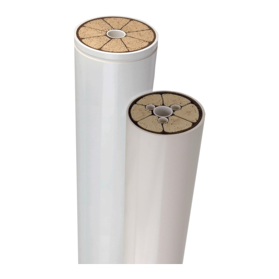
UF membrane Module body (Hollow) Interconnector O-Rings End caps Shim (s) ** as necessary End-Connectors UF Element Pressure Vessel *according to surface area ® L Series horizontal – Assembly Instructions 2.2(2019-06) E inge dizzer Page 18 of 60 © inge GmbH... -
Page 19: Functional Description
Module body Cylindrical shell, PVC-U white PVC-U white For filtrate-sided connection between multiple UF elements in line Interconnector O-Rings EPDM O-Rings ® L Series horizontal – Assembly Instructions 2.2(2019-06) E inge dizzer Page 19 of 60 © inge GmbH... -
Page 20: Technical Data
Horizontal system. 3.1.3.2 Interconnector ® Interconnector Set for dizzer L 40 PB → Please see the datasheet ‚Interconnector’ for horizontal systems. ® L Series horizontal – Assembly Instructions 2.2(2019-06) E inge dizzer Page 20 of 60 © inge GmbH... -
Page 21: Dizzer ® L 55
UF membrane Module body (Hollow) Interconnector O-Rings End caps Shim (s) ** as necessary End-Connectors UF Element Pressure Vessel *according to surface area ® L Series horizontal – Assembly Instructions 2.2(2019-06) E inge dizzer Page 21 of 60 © inge GmbH... -
Page 22: Functional Description
Module body Cylindrical shell, PVC-U white PVC-U white For filtrate-sided connection between multiple UF elements in line Interconnector O-Rings EPDM O-Rings ® L Series horizontal – Assembly Instructions 2.2(2019-06) E inge dizzer Page 22 of 60 © inge GmbH... -
Page 23: Technical Data
Interconnector Set for dizzer L 55 module ® → Please see the datasheet ‚Connecting kit for dizzer 0.9 MB 55 for horizontal pressure vessel’. ® L Series horizontal – Assembly Instructions 2.2(2019-06) E inge dizzer Page 23 of 60 © inge GmbH... -
Page 24: Loading, Transport And Storage
‘DS Packaging dL40PB’ and ‘DS Packaging dL55Horizontal’ for modules ® of the dizzer L Series. Condition of shipment and box type are subject to modification by inge GmbH without notice. ® L Series horizontal – Assembly Instructions 2.2(2019-06) E inge... -
Page 25: Warnings
Danger of crushing and shearing from work in the danger zone. Note the specified number of persons required! Wear safety gloves! Wear safety shoes! ® L Series horizontal – Assembly Instructions 2.2(2019-06) E inge dizzer Page 25 of 60 © inge GmbH... - Page 26 Determine the weight of the module in use! Always note the locally applicable maximum permissible load of persons! Note the specified number of persons required! ® L Series horizontal – Assembly Instructions 2.2(2019-06) E inge dizzer Page 26 of 60 © inge GmbH...
-
Page 27: Loading
Low packages over which other, higher packages could tip in case of emergency braking must not be positioned at the bulkhead. ® L Series horizontal – Assembly Instructions 2.2(2019-06) E inge dizzer Page 27 of 60 © inge GmbH... -
Page 28: Transport
Check the maximum floor load of the planned warehouse storage area. The details on the weights can be found in the delivery papers. ® L Series horizontal – Assembly Instructions 2.2(2019-06) E inge dizzer Page 28 of 60 © inge GmbH... -
Page 29: Loading / Assembly
Danger of crushing and shearing from work in the danger zone. Note the specified number of persons required! Wear safety gloves! Wear safety shoes! ® L Series horizontal – Assembly Instructions 2.2(2019-06) E inge dizzer Page 29 of 60 © inge GmbH... - Page 30 Danger of tripping and impact from pallets, packages and assembled parts at the construction site. Wear a safety helmet! Wear safety shoes! ® L Series horizontal – Assembly Instructions 2.2(2019-06) E inge dizzer Page 30 of 60 © inge GmbH...
-
Page 31: General Specifications
L Series in pressure vessels at least 2 people are required. Personnel Requirements for Other Tasks Unless otherwise specified, all other tasks require one person. ® L Series horizontal – Assembly Instructions 2.2(2019-06) E inge dizzer Page 31 of 60 © inge GmbH... -
Page 32: Tools And Consumables
Glycerin (>97%) Further required tools depend on the design of the existing pressure vessel and must be determined by the pressure vessel supplier. ® L Series horizontal – Assembly Instructions 2.2(2019-06) E inge dizzer Page 32 of 60 © inge GmbH... -
Page 33: Preparing For Assembly
L Series to be installed, disassembled and operated safely. CAUTION DANGER OF INJURY! Danger of injury due to constricted space. Provide for sufficient space! ® L Series horizontal – Assembly Instructions 2.2(2019-06) E inge dizzer Page 33 of 60 © inge GmbH... -
Page 34: Protecting The Work Area
Danger of injury to bystanders, machines and devices in the work area. Protect the work area against unauthorized access and against machines and devices that are not involved! ® L Series horizontal – Assembly Instructions 2.2(2019-06) E inge dizzer Page 34 of 60 © inge GmbH... -
Page 35: Checking The Delivery
Damaged modules and parts with written approval from inge GmbH with a specific reference to the damaged module or part inge GmbH decides on the procedure (approval or block) for all damaged modules or parts that have not been approved. -
Page 36: Checking The Delivery For Completeness
Note the position of the module within the rack (line, train/unit, side, position) together with the module serial number. Promptly inform your contact at inge GmbH if the number of pieces differs between the packing list and the existing packages. -
Page 37: Loading Of Dizzer L 40 Pb In A Pressure Vessel
/ tub Let the module empty for some minutes (typically 5 min.) Store the modules horizontally on a clean surface ® L Series horizontal – Assembly Instructions 2.2(2019-06) E inge dizzer Page 37 of 60 © inge GmbH... - Page 38 ® Damage to the dizzer L modules due to thermal expansion may occur and is not covered by the warranty. ® L Series horizontal – Assembly Instructions 2.2(2019-06) E inge dizzer Page 38 of 60 © inge GmbH...
-
Page 39: Module Installation
New / unused inge Interconnector Sets need to be applied for installation. NOTE The bypass pipes (PB) do not need to be aligned between modules. ® L Series horizontal – Assembly Instructions 2.2(2019-06) E inge dizzer Page 39 of 60 © inge GmbH... - Page 40 Insert 1 module into pressure vessel (30-50 cm should remain outside). ® Hold the module and insert an inge interconnector into the module. ® L Series horizontal – Assembly Instructions 2.2(2019-06) E inge dizzer Page 40 of 60 © inge GmbH...
- Page 41 2 module and push the package carefully into the pressure vessel (30-50 cm should remain outside) ® L Series horizontal – Assembly Instructions 2.2(2019-06) E inge dizzer Page 41 of 60 © inge GmbH...
- Page 42 Shims have to be inserted on the end-cap- interconnector(s) on both sides – as needed – in order to compensate any length differences and prevent module movement during operation. ® L Series horizontal – Assembly Instructions 2.2(2019-06) E inge dizzer Page 42 of 60 © inge GmbH...
-
Page 43: Loading Of Dizzer L 55 In A Pressure Vessel
/ tub Let the module empty for some minutes (typically 5 min.) Store the modules horizontally on a clean surface ® L Series horizontal – Assembly Instructions 2.2(2019-06) E inge dizzer Page 43 of 60 © inge GmbH... - Page 44 ® Damage to the dizzer L modules due to thermal expansion may occur and is not covered by the warranty. ® L Series horizontal – Assembly Instructions 2.2(2019-06) E inge dizzer Page 44 of 60 © inge GmbH...
-
Page 45: Module Installation
Loading of modules into one pressure vessel must be performed on the same day. NOTE ® New / unused inge Horizontal Connecting Kits need to be applied for installation. ® L Series horizontal – Assembly Instructions 2.2(2019-06) E inge dizzer Page 45 of 60 © inge GmbH... - Page 46 (30-50 cm should remain outside). Hold the module and attach the second spacer ring over the protruding end of the module ® L Series horizontal – Assembly Instructions 2.2(2019-06) E inge dizzer Page 46 of 60 © inge GmbH...
- Page 47 (30-50 cm should remain outside) Hold the module and attach the second spacer ring over the protruding end of the module ® L Series horizontal – Assembly Instructions 2.2(2019-06) E inge dizzer Page 47 of 60 © inge GmbH...
- Page 48 Put the 3 module on the interconnector of the 2 module and push the package carefully into the pressure vessel (30-50cm should remain outside) ® L Series horizontal – Assembly Instructions 2.2(2019-06) E inge dizzer Page 48 of 60 © inge GmbH...
- Page 49 3 module and push the package carefully into the pressure vessel (30-50 cm should remain outside) ® L Series horizontal – Assembly Instructions 2.2(2019-06) E inge dizzer Page 49 of 60 © inge GmbH...
- Page 50 Step Activity Figure Hold the module and attach the second spacer ring over ® the protruding end of the module and insert the last inge interconnector into the 4 module Insert the complete package into the pressure vessel End-caps Re-install end-connectors following instructions of the pressure vessel manufacturer or those specified in the Operation Manual of the plant.
-
Page 51: Service And Maintenance
WARNING CONSIDERABLE DANGER OF INJURY! Cutting and impact injuries from sharp corners and edges. Wear safety gloves! Wear safety shoes! ® L Series horizontal – Assembly Instructions 2.2(2019-06) E inge dizzer Page 51 of 60 © inge GmbH... - Page 52 Determine the weight of the module in use! Always note the locally applicable maximum permissible load of persons! Note the specified number of persons required! ® L Series horizontal – Assembly Instructions 2.2(2019-06) E inge dizzer Page 52 of 60 © inge GmbH...
-
Page 53: Checks During Operation
When exchanging parts, only genuine parts from inge GmbH are permitted to be used. Returning Modules Returns shall only be accepted if this has been agreed in advance with inge GmbH and authorized in writing. Returns that have been previously agreed and approved by inge GmbH are subject to the following mandatory requirements: ... -
Page 54: Disassembly And Disposal
WARNING CONSIDERABLE DANGER OF INJURY! Cutting and impact injuries from sharp corners and edges. Wear safety gloves! Wear safety shoes! ® L Series horizontal – Assembly Instructions 2.2(2019-06) E inge dizzer Page 54 of 60 © inge GmbH... -
Page 55: Disassembly
The disassembly is performed in reverse order to the assembly. A special tool could be useful for the removal ® of the modules. If any information on the procedure is required please contact inge → For details, see section 5 Loading / Assembly Disposal ®... -
Page 56: Customer Service
NOTE A detailed list of the individual components can be found in the spare parts lists. The spare parts lists will be made available to you by inge GmbH on request. ® L Series horizontal – Assembly Instructions 2.2(2019-06) E inge... -
Page 57: Technical Documentation
Spare parts lists ® refers to the system supplier for further documents (for example ‚System As a component supplier, inge Operating Instructions‘). ® L Series horizontal – Assembly Instructions 2.2(2019-06) E inge dizzer Page 57 of 60 © inge GmbH... - Page 58 Technical Documentation Appendix: Membrane Loading Logbook ® L Series – Assembly Instructions 2(2019-03) E inge.1(2019-01) E inge dizzer Page 58 of 60 © inge GmbH...
- Page 59 UF Train – UF Element Position (assuming pressure vessel with 4 UF Shims Interconnector Membrane elements) Pressure Check Vessel # General Notes: ® L Series horizontal – Assembly Instructions 2.2(2019-06) E inge dizzer Page 59 of 60 © inge GmbH...
- Page 60 The descriptions, designs, data and product information contained herein are presented in good faith and are based on inge GmbH’s current knowledge and experience. inge GmbH cannot accept any liability for the accuracy of this product information, which is provided at no charge and for guidance only.
Need help?
Do you have a question about the dizzer L Series and is the answer not in the manual?
Questions and answers