Table of Contents
Advertisement
Quick Links
Advertisement
Table of Contents

Summary of Contents for HARTING HAIIC MICA
- Page 1 HARTING HAIIC MICA Hardware Development Guide...
- Page 2 No part of this manual may be reproduced in any form (print, photocopy, microfilm or any other process), processed, duplicated or distributed by means of electronic systems without the written permission of HARTING Electric GmbH & Co. KG, Espelkamp. Subject to alterations without notice.
-
Page 3: Table Of Contents
24V Supply ....................4 LED Status Display ................... 4 GPIO ........................5 MICA Customizable Circuit Board ............... 9 Technical Description ................9 Thermal Behavior ..................9 Front Bezel ....................11 Attachments ......................12 HAIIC MICA Hardware Development Guide, Edition 2016... -
Page 4: Power Supply
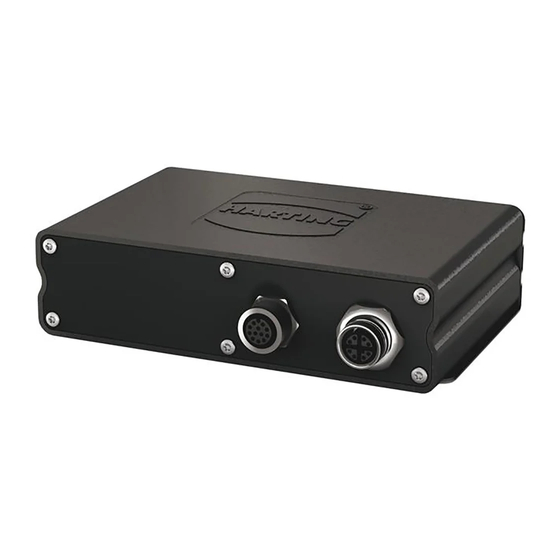
8 pin outlet (B) 24V Supply Alternatively the MICA can be supplied with electricity over a Harting breakout cable (24 VDC) with a M12 plug-in connector where the input cable is grey/pink and the ground wire is red/blue. When using the M12 plug-in connector observe the assignment of the pins. Then connect the M12 connector to a power supply. -
Page 5: Gpio
Caution: GPIO channels can be reconfigured from Input to Output in software. Check that all channels are in default configuration when attaching them to a new hardware device. Figure 2: Assignment of the GPIO Channels in Harting Breakout Cable HAIIC MICA Hardware Development Guide, Edition 2016... - Page 6 HAIIC MICA Hardware Development Guide You can load a single channel with max. 50mA, a combination of channels with 250mA to avoid an overheating of the TLE chip behind the channels. You can use the GPIO channels as inputs for e.g. signals: Pins HS1 (OUT0) –...
- Page 7 Pins HS1 (OUT0) – HS4 (OUT3) for a high side switch Pins LS1 (OUT6) – LS2 (OUT7) for a low side switch Pins SWD1 (D4) / SWD2 (D5) and SWS1 (S4) / SWS2 (S5) for a configurable switch HAIIC MICA Hardware Development Guide, Edition 2016...
- Page 8 HAIIC MICA Hardware Development Guide Figure 3: Color Coding of Channels in Harting Breakout Cable (see attachment 1) HARTING IT Software Development...
-
Page 9: Mica Customizable Circuit Board
USB 2.0 connection GPIO GPIO Reserved for future use GPIO Ground Thermal Behavior At the bottom of the functional module a thermal interface material (for example Bergquist GF 1500) should be applied. HAIIC MICA Hardware Development Guide, Edition 2016... - Page 10 HAIIC MICA Hardware Development Guide Figure 4: Printed Circuit Board (PCB) Figure 5 Allocation of Connector Pins (top to bottom) HARTING IT Software Development...
-
Page 11: Front Bezel
The front bezel can be customized with the proper connectors to fit your application. The po- sition of the customizable circuit board in relationship to the front bezel is shown in figure 6. HAIIC MICA Hardware Development Guide, Edition 2016... -
Page 12: Attachments
HAIIC MICA Hardware Development Guide 4 Attachments Figure 7: M12 A-coded Cable Assembly of Harting Breakout Cable HARTING IT Software Development... - Page 13 HAIIC MICA Hardware Development Guide Document Version 1.3.0 Chapter LED Display has been added. HAIIC MICA Hardware Development Guide, Edition 2016...