Advertisement
GasVac
This document is not contractual and the equipment specification may be modified at any time without prior notice.
E:
sales@gds-technologies.co.uk
GDS TECHNOLOGIES LTD
|
FUSION POINT
SINGLE LINE NETWORK
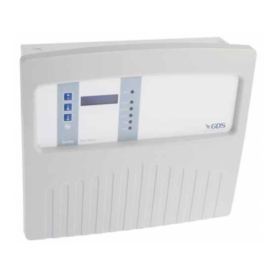
GAS SAMPLE UNIT
OPERATING HANDBOOK
T:
+44 (0)113 286 0166
|
ASH LANE
|
GARFORTH
|
LEEDS
311
®
www.gds-technologies.co.uk
|
LS25 2GA
|
UK
T E C H N O L O G I E S
C1732
Manual No. 330DIC
Issue A v1
Advertisement
Table of Contents

Subscribe to Our Youtube Channel
Related Manuals for GDS GasVac 311


Summary of Contents for GDS GasVac 311
- Page 1 GAS SAMPLE UNIT OPERATING HANDBOOK This document is not contractual and the equipment specification may be modified at any time without prior notice. sales@gds-technologies.co.uk +44 (0)113 286 0166 www.gds-technologies.co.uk GDS TECHNOLOGIES LTD FUSION POINT ASH LANE GARFORTH LEEDS LS25 2GA...
-
Page 2: Table Of Contents
Contents System Overview ........................3 Installation, Operation ......................4 Access to the Menu ......................5 Technical Specification ....................... 6-7 Service/Routine Attention ...................... 8... -
Page 3: System Overview
System Overview The GasVac 311 system is designed to monitor gas levels in situations where the positioning of conventional gas sensors may not be practical. This may be due to equipment security, cable routing, access for detector head installation/maintenance, or harsh environment, or a cost effective means of monitoring plant rooms, supermarkets, cool stores and designated hazardous areas, such as tunnels, marine applications, or underground/high level voids. -
Page 4: Installation, Operation
Installation The unit should be mounted in a position which is accessible and in the field of vision. Mains should be from a fused supply (2A) and connected to the mains input terminals of the power supply unit. The vent port should be piped to atmosphere without reduction. This will prevent possible back pressure affecting the sensor reading. -
Page 5: Access To The Menu
Pressing 1 or 3 will allow for output to be adjusted to 4mA and 20mA as measured on test pins 8+9. Changes to gas type and range can be made by connecting GDS RS232 pod Part No. 160-510 to J3 and using a PC running hyper terminal at 4800 baud. -
Page 6: Technical Specification
Technical Specification POWER SUPPLY Input 230/115v AC – 50/60 Hz - 24v DC CONSUMPTION 70W full alarm INDICATORS Gas level readout – two line alpha numeric back lit display Power – green L.E.D Low, High, Over-range alarm – red L.E.D System fault / Flow fail –... - Page 7 PUMP Sample pump – 24v DC brushless-diaphram OPERATING TEMPERATURE -10 to +45˚C SAMPLE TEMPERATURE -10 to +50˚C – high temperature versions available RESPONSE TIME 20 to 80 seconds INTAKE MODULES (part No. 008-556 Design Reg 6009030) All weather Orientation – any Size –...
-
Page 8: Service/Routine Attention
Service Routine Attention The owner or occupier of the site should place the supervision of the system in the charge of a responsible executive, whose duty it should be to ensure the day to day operation of the system and to lay down the procedure for dealing with a gas alarm or fault warning. - Page 9 This document is not contractual and the equipment specification may be modified at any time without prior notice. sales@gds-technologies.co.uk +44 (0)113 286 0166 www.gds-technologies.co.uk GDS TECHNOLOGIES LTD FUSION POINT ASH LANE GARFORTH LEEDS LS25 2GA...
Need help?
Do you have a question about the GasVac 311 and is the answer not in the manual?
Questions and answers