Table of Contents
Advertisement
Quick Links
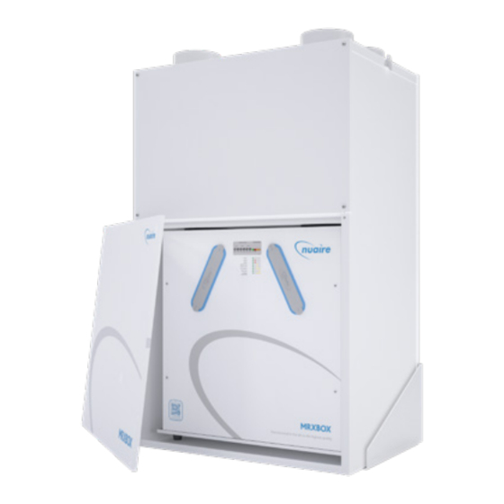
MRXBOXAB-ECO4-1Z (Standard Unit)
MRXBOXAB-ECO4-1Z-OH (Opposite hand Unit)
Mechanical Ventilation Units with Heat Recovery
Installation and Maintenance
1.0 INTRODUCTION
The ECO4-1Z range of units are designed to offer improved sound
levels and an aesthetically pleasing installation by housing a
Mechanical Ventilation with Heat Recovery (MVHR) unit and
attenuator inside an acoustically lined enclosure.
The MVHR unit is fitted with two independent fans to provide
mechanical supply and extract ventilation, each fan has full speed
control for background and boost ventilation rates. To recover heat
from the extract air, the heat exchanger block is utilised. The heat
exchanger can recover up to 95% of the normally wasted heat.
The units also incorporate an integral humidistat and frost protection,
see sections 7.1 & 9.1 for details.
The unit is not supplied with any mounting brackets; a suitable
mounting structure with means of securing the unit in place is
required.
2.0 INSTALLATION
Installation must be carried out by competent personnel in accordance
with the appropriate authority and conforming to all statutory
governing regulations. All mains wiring must be in accordance with the
current I.E.E. Regulations, or the appropriate standards. Ensure that the
mains supply (Voltage, Frequency and Phase) complies with the rating
label.
Please note a clear working space is required around the installed unit
to allow the cover to be removed and provide sufficient access for
maintenance such as filter change. A minimum of 480mm is required in
front of the unit.
The fan must be installed indoors, on a suitable structure away from
direct sources of frost, heat and water spray or moisture generation. For
a vibration-free result the unit must be mounted to a solid structure.
Figure 3. Mounting point locations.
4x M10 Flanged head bolts
protruding from base to be
accomodated in structure design.
Condensate Drain connection
(standard hand configuration).
For opposite hand configuration position
will be mirrored to the other side.
Summer / Winter Cable entry point.
nuaire.co.uk
029 2085 8400
726
=
43
143
48
Figure 1. Airflow through unit (Standard unit).
Exhaust air
from house
to outside
Figure 2. Airflow through OH unit (Opposite hand unit).
Supply air
to house
=
43
2x Rivet Heads
48
Mains Cable Connection
28. 07. 20. Leaflet Number 671838
The EMC Directive
2014/30/EU
The Low Voltage
Directive
2014/35/EU
Intake air
from outside
Supply air
to house
Extract air
from house
Extract air
from house
Exhaust air
from house
to outside
Intake air
from outside
2x Hatched regions details
compulsory support areas,
further support may be required
depending on structure design
(supplied by others).
4x M8 Mounting Points
Note:
Any Items being accomodated in structure design should
include sufficient clearance to allow for assembly tolerances
and for ease of installation when positioning on site.
1
Advertisement
Table of Contents

Related Manuals for NuAire MRXBOXAB-ECO4-1Z


Summary of Contents for NuAire MRXBOXAB-ECO4-1Z
- Page 1 MRXBOXAB-ECO4-1Z (Standard Unit) MRXBOXAB-ECO4-1Z-OH (Opposite hand Unit) The EMC Directive Mechanical Ventilation Units with Heat Recovery 2014/30/EU The Low Voltage Directive Installation and Maintenance 2014/35/EU 1.0 INTRODUCTION Figure 1. Airflow through unit (Standard unit). The ECO4-1Z range of units are designed to offer improved sound...
- Page 2 Installation and Maintenance The MRXBOXAB-ECO4-1Z Range of Units IMPORTANT 2.3 Transportation Fixings To prevent damage during transit and installation, the product is The unit must remain switched on at all times to maintain shipped with two transportation brackets, these are attached to the ventilation within the dwelling.
- Page 3 A maximum of 300mm should be used on each leg. Nuaire recommend MVHR-DRAIN be used as the primary condensate take-off (see Figure 8 & ). To prevent condensation on the outside of the outside air inlet duct and the air outlet duct from the unit, these ducts should be insulated.
- Page 4 Installation and Maintenance The MRXBOXAB-ECO4-1Z Range of Units 2.8 ADF 2010 Ventilation Calculations Design of MVHR Step 3: The required airflow rates are as follows: Systems The maximum whole dwelling extract ventilation rate (e.g. boost) • should be at least the greater of step 1 and step 2. Note that the The MVHR system has been sized for the winter period.
- Page 5 Installation and Maintenance The MRXBOXAB-ECO4-1Z Range of Units 4.0 DUCTING ARRANGEMENTS - STANDARD CONFIGURATION Figure 11. Typical ducted arrangement for a unit using circular ducting. Exhaust air from *Insulated kitchen/bathroom to extract duct. outside via louvre grille. Minimum distance as specified Top of ceiling void.
- Page 6 Installation and Maintenance The MRXBOXAB-ECO4-1Z Range of Units 5.0 ELECTRICAL CONNECTION Figure 13. PCB Details IMPORTANT Wiring is for reference purposes only as the connections shown are factory fitted. The unit is pre-wired with a 1.4 metre long fly lead.
- Page 7 Installation and Maintenance The MRXBOXAB-ECO4-1Z Range of Units 6.0 ECOSMART CONTROLS 7. Adjustment valves should be locked in place to prevent further adjustment. A single Ecosmart connection point is available through the base panel 8. Once commissioned, the home owner / tenant should be informed...
- Page 8 The product warranty applies to the UK mainland and in accordance with Clause 14 of our Conditions of Sale. Customers purchasing from outside of the UK should contact Nuaire International Sales office for further details. nuaire.co.uk 029 2085 8400 28.
Need help?
Do you have a question about the MRXBOXAB-ECO4-1Z and is the answer not in the manual?
Questions and answers