
Related Manuals for IBEKO POWER DV Power RMO25T

Summary of Contents for IBEKO POWER DV Power RMO25T
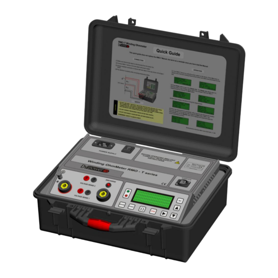
- Page 1 RMO25T W I N D I N G O H M M E T E R & T A P C H A N G E R T E S T S E T Manual BEKO OWER...
-
Page 2: Table Of Contents
IBEKO POWER AB explicitly exonerates itself from all liability for mistakes in this Manual. IBEKO POWER AB translates this Manual from its source language English into a number of other languages. Any translation of this Manual is done for local requirements, and in the event of a dispute between the English and any... -
Page 3: Introduction
RMO25T Introduction, Safety Instructions Introduction This Manual contains helpful instructions on how to use RMO25T in a safe, proper and efficient way. Following these instructions can help you avoid dangerous situations, repair costs and other miss happenings due to incorrect operation. Furthermore it ensures the reliability and life cycle of your RMO25T. -
Page 4: Designated Use
If RMO25T is opened by the customer, all guarantees are invalidated. If RMO25T seems to be functioning improperly, please contact the IBEKO POWER AB (refer to section ”Manufacturer Contact Information”) after first checking the section Error Messages . ... - Page 5 RMO25T Designated Use, Functionality The inductance value of a transformer depends on the current injected in the windings. When the transformer is saturated the inductance is minimized. A transformer is normally designed to reach saturation when the current is 1,2 times the peak value of the no-load current. The no-load current is normally in the range of 0,2 % to 5 % of the nominal winding current.
- Page 6 RMO25T Designated Use, Functionality Tap Changer Test The TapC menu offers a user friendly way of measuring winding resistance in tap changers. The RMO25T test set measures the winding resistance of individual taps of a power transformer‟s tap changer, and checks whether the On-Load Tap Changer (OLTC) switches without a discontinuity. In the moment the tap is changed from tap to tap, the device detects the sudden, very short drop of the current flow.
-
Page 7: Description
RMO25T Description Description Front Panel Components Display button to ENTER confirm the defined test button to parameters, Language, scroll between Time and Date the Current menu, the TapC menu and the Memory menu buttons UP/DOWN to select a menu and set test parameters Ω... - Page 8 RMO25T Description Mains power and ground connectors Connector for mains power supply Power switch I In this position, RMO25T is connected to the mains power supply. 0 In this position, RMO25T is separated from the mains power supply with both poles. Earth/ground connector.
- Page 9 RMO25T Getting Started Figure 5-3: The Time menu showing RMO25T‟s internal time and date Move the cursor to the position of your choice using the buttons, and change the value with LEFT/RIGHT button. ENTER Pressing to confirm, returns you to the Main menu. ENTER Pressing to cancel, returns you to the Main menu.
-
Page 10: Getting Started
RMO25T Getting Started Getting Started Current test Connecting a Test Object to the RMO25T Before you connect a test object to RMO25T, make sure that: • The test object is disconnected or separated from its circuit in accordance with the national safety regulations and is properly grounded to protective earth. - Page 11 RMO25T Getting Started Figure 6-2: Connecting a test object to RMO25T Testing of a Delta-delta winding resistance is usually a very time consuming procedure. This is because the two windings resemble two closed loop inductors. When energy is brought into the inductors, this energy (in the form of D.C.
- Page 12 RMO25T Getting Started Setting the Measurement Parameters Directly after the first display RMO25T automatically changes to the Current menu and the green LED lights up. Test current Memory position Figure 6-4: The Curr menu Menu name Test duration time Memory Time and Date Before a test can be started, the following needs to be defined in the Current menu: ...
- Page 13 RMO25T Getting Started During the test, both the green and the red LEDs flash alternately and the buzzer beeps. When the current is stabilized, RMO25T starts the measurement of the test object resistance. Figure 6-6: Memory The Curr menu during the test The display shows test current (here ) and the effective value of the measured resistance (here 498 mA...
- Page 14 RMO25T Getting Started Note: Using DV-Win the results could be stored to a PC, where reading interval results is adjustable. Results will be shown in a table in Excel format with an option to perform additional edit and graphic presentation. Using DV-Win after the test in order to transfer the results from selected internal memory location to a PC will allow transfer of the last test result only.
- Page 15 RMO25T Getting Started Tap Changer test Using RMO25T‟s Tap Changer (TapC) menu the winding resistance of individual taps of a power transformer‟s tap changer can be measured. Also it can be used to control the transformer tap changer. This is a user friendly way of winding resistance measurement and tap changer control, since automatic measurement is possible with no need to remove the current between each tap change.
- Page 16 RMO25T Getting Started Tap Changer test with RMO25T Before a test can be started, test current and memory position need to be defined using the TapC menu. Once these parameters are defined, press to change to the Ready state. ENTER Figure 6-11: The Ready state before the test...
- Page 17 RMO25T Getting Started Repeat this procedure as often as needed until the results for RIPPLE and RESISTANCE are obtained for all Tap Changer positions. Test is completed pushing the button. STOP When measurement is completed (after pressing the button) RMO25T switches to the TapC STOP menu and starts current discharging.
- Page 18 RMO25T Getting Started C A U T I O N DO NOT DISCONNECT LEADS BEFORE “DISCHARGING” MESSAGE IS DISAPPEARED FROM THE DISPLAY AND THE DISCHARGING DIODE AND BUZZER ARE OFF. Note: Using DV-Win the results could be stored to a PC, where reading interval results is adjustable. Results will be shown in a table in Excel format with an option to perform additional edit and graphic presentation.
- Page 19 RMO25T Getting Started Viewing Results of Previous Tests RMO25T stores up to 500 test results. They can be viewed using the Memory menu at memory positions from 0 to 499. Go to Memory menu using button. Selecting a memory position on the Memory menu displays: •...
- Page 20 RMO25T Getting Started Figure 6-23: The Print menu showing first and last memory position and Date and Time of printing Settings of the printer as well as look of the RMO25T Test Report are given at figure above. Duty Cycles During tests, RMO25T generates a high DC current that heats up the test set.
-
Page 21: Dv-Win Software
RMO25T DV-Win Software DV-Win Software DV-Win is a Windows program for working with Winding Ohmmeters RMO25T. It enables the two-way communication between RMO25T and a PC over the USB. DV-Win supports the following functions: Controlling and starting RMO25T when the tests are performed from the PC; the results could be stored to PC;... - Page 22 RMO25T DV-Win Software - Click on ”OK”, - Follow the instructions displayed on the screen, - When the installation process has been completed, - Exit the program. Starting DV-Win Turn RMO25T on. Start DV-Win: - Click on ”Start”, - Click on ”Programs”, - Click on ''DV-Win‟‟, or double click at the DV-Win icon on the desktop.
- Page 23 RMO25T DV-Win Software 7.4 Test info Test object You can use the Test object field to store test results in a database, so that they could later be recalled for analysis and comparison with previous test results. Test information In this field you can enter basic information about the operator, supervisor and the Job ID of a certain test.
- Page 24 RMO25T DV-Win Software After all connections are properly done and DV-Win is run, chose the Current mode clicking on the Current tab. Set the measurement parameters such as: - Connections - marking of the winding of the transformer under test - Test current - Test duration time - Memory location...
- Page 25 RMO25T DV-Win Software By selecting “Automatic” option and time interval (sample time), the last measured result will be transferred from RMO25T to PC at the chosen time intervals. By selecting “Manual” option, the last measured result will be transferred from RMO25T to PC upon pressing the Ω...
- Page 26 RMO25T DV-Win Software 7.6 Tap Changer Mode Using a PC together with RMO25T device in the Tap Changer mode it is possible to conclude about tap changer conditions analyzing a graph which represents dynamic resistance during tap changes. Figure above shows connections between a PC and RMO25T and also connection to the transformer under test.
- Page 27 RMO25T DV-Win Software Graphic function is available in the “on-line” or “off-line” mode. Using both off-line and on-line modes, test current values during the transition from tap to tap are shown on the graph. Graph control window contains options and commands to control graph display. Graph is displayed in separate window, where user can zoom in and zoom out interesting parts of the graph.
- Page 28 RMO25T DV-Win Software Continuous recording Selecting continuous recording option enables recording of all transitions without resistance measurement in each tap position. After initial resistance measurement is done and a message is shown, it is necessary to change the tap positions. The graph is not displayed until the test is stopped. Once the STOP button is pressed, all the transitions (OLTC dynamic resistance graph) will be displayed.
- Page 29 RMO25T DV-Win Software When the tap position is changed the graph with the test current during the change will be displayed. That graph represents dynamic resistance during the change from tap to tap. When the graph is displayed and R is stable press OMEGA button to measure resistance in the new tap changer position.
- Page 30 RMO25T DV-Win Software Once the measurement is completed, save the data. The graph can be saved as the graph with three different resolutions: High (resolution is 0,1 ms) Medium (resolution is 1 ms) Low (resolution is 4 ms) The graph analysis The graph can be analyzed “online”...
- Page 31 RMO25T DV-Win Software Print Print the graph to the local printer. Zoom In To zoom in the graph, each click will zoom in the graph for 20 % related to the center of the graph. Zoom Out To zoom out the graph, each click will zoom out the graph for 20 % related to the center of the graph. Undo Return to previous zoom level.
- Page 32 RMO25T DV-Win Software Cursors The cursors are enabled checking Cursor 1 and/or Cursor 2 check boxes. When enabled, each cursor shows time and current values of the cursor position. If both cursors are enabled, then the time and current difference are also displayed. Cursors movement is done by holding the left mouse button and dragging the cursor along the graph.
- Page 33 RMO25T DV-Win Software Download With this command the results from the internal RMO25T memory can be transferred to the PC. The transfer is possible only if the serial port RMO25T is connected with the appropriate cable to the PC. Note: OLTC graph or dynamic resistance can not be downloaded from internal memory of the RMO25T since they are not saved there.
- Page 34 RMO25T DV-Win Software Date from – up to After choosing this option, a new window appears. It provides a choice to select a time interval when the measurements were done. The results obtained during the time period between the chosen dates, including the chosen dates, are going to be transferred to the PC.
- Page 35 RMO25T DV-Win Software The results table The results from internal memory of RMO25T are transferred to the PC in the data table; the following layout will be displayed: Current mode - Date and Time : the date and the time of the test - Current : the real test current - Voltage 1...
-
Page 36: Error Messages
RMO25T Error Messages Error Messages Any operational error is indicated by a red LED and accompanied by an alarm. Furthermore, the display indicates an error status message. To stop the alarm buzzer, remove the status message on the display, and return to the Current or TapC menu, press the button. - Page 37 RMO25T Error Messages Error Messages "Polarity" The Error messages "Polarity" is displayed if: The Voltage sense cables are connected with opposite polarity either on the side of a device, or the side of test object, and the signal is higher than 60mV. In some cases discharge LED can light alternately.
- Page 38 The message "Error printer" is displayed if hardware error is apparent at the printer. Check weather black shaft is in proper position. If yes and the error occurs repeatedly, please contact IBEKO POWER AB (refer to section ”Manufacturer Contact Information”).
-
Page 39: Technical Data
RMO25T Technical Data Technical Data Mains Power Supply - Connection according to IEC/EN60320-1; UL498, CSA 22.2 110 V – 240 V AC, +10 % – -15 % - Voltage single phase - Frequency 50 / 60 Hz Output data 5 mA – 25 A DC - Test current - Typical Accuracy ±... -
Page 40: Accessories
RMO25T Technical Data Accessories Article No Standard Current cables 2 x 10 m, 10 mm with battery clips Sense cables 2 x 2 x 10 m, 2,5 mm with alligator clips Current connection cable 1 x 5 m 10 mm DV-Win PC software including USB cable Mains power cable Ground (PE) cable...
Need help?
Do you have a question about the DV Power RMO25T and is the answer not in the manual?
Questions and answers