Advertisement
Quick Links
This is a safety alert symbol and should never be ignored. When you see this symbol on labels or in
manuals, be alert to the potential for personal injury or death.
Table of Contents
Safety Precautions ......................................................2
Installation ...................................................................2
Electrical Connections .................................................4
Start-Up Procedure......................................................8
Homeowner's Information .........................................11
Improper Installation, adjustment, alteration, service
or maintenance will void the warranty. The qualified
installer or agency must use factory-authorized kits
or accessories when modifying this product. Refer to
the individual instructions packaged with the kits or
accessories when installing.
Installation or repairs made by unqualified persons CAN
result in hazards to you and others. Installation MUST
conform with local building codes and with the National
Electric Code NFPA 70/ANSI C1-1993 or current edition
and Canadian Electrical Code Part 1 CSA.
Manufactured By
Allied Air Enterprises LLC
A Lennox International, Inc. Company
215 Metropolitan Drive
West Columbia, SC 29170
507523-01
INSTALLATION INSTRUCTIONS
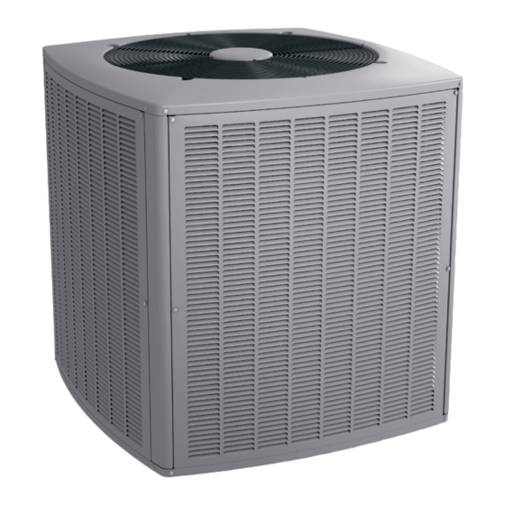
4SCU20LX UNITS
(R410A REFRIGERANT)
This manual must be left with the homeowner for future reference.
CAUTION
WARNING
Save these instructions for future reference
These instructions are intended as a general guide and
do not supersede national, state or local codes in any
way.
These instructions must be left with the property
owner.
Before installing, modifying, or servicing system, main
electrical disconnect switch must be in the OFF position.
There may be more than 1 disconnect switch. Lock out
and tag switch with a suitable warning label. Electrical
shock can cause personal injury or death.
Issue 1831
NOTE
WARNING
*P507523-01*
(P) 507523-01
Page 1 of 11
Advertisement

Summary of Contents for Allied Air 4SCU20LX
-
Page 1: Table Of Contents
National Electric Code NFPA 70/ANSI C1-1993 or current edition and Canadian Electrical Code Part 1 CSA. Manufactured By *P507523-01* Allied Air Enterprises LLC A Lennox International, Inc. Company 215 Metropolitan Drive (P) 507523-01 West Columbia, SC 29170... -
Page 2: Safety Precautions
These units are designed for use in residential and light by 15 ft. of field-supplied tubing. For proper unit operation, commercial type buildings. Units should be installed with check refrigerant charge using charging information approved indoor matches listed in the Air-Conditioning, located on control box cover. - Page 3 DO LOCATE THE UNIT: Filter Drier • With proper clearances on sides and top of unit a The filter drier is very important for proper system operation minimum of 12” on the three sides, service side should and reliability. If the drier is shipped loose, it must be be 24”...
-
Page 4: Electrical Connections
Leak Check Place service valve cap and torque to: Valve Size Torque (ft.-lb.) WARNING 3/8 Valve 8-11 Never use oxygen to pressurize or purge refrigerant 3/4 Valve 12-15 lines, fire or explosion can occur causing injury or 7/8 Valve 15-20 property damage Table 2. - Page 5 Outdoor Control Seven-Segment Display and Remove access panel to gain access to unit wiring. Extend wires from disconnect through power wiring hole provided Push Button and into unit control box. Flexible conduit is required for the Information concerning the outdoor control seven-segment swing out control box feature.
- Page 6 OUTDOOR UNIT CONNECT CONDUIT TO CUTOUT AND ROUTE HIGH VOLTAGE WIRING CONNECTS TO RAST 6-PIN CONNECTOR GROMMET AND PROVIDED RAST CABLE TIE. 6-PIN CONNECTOR ROUTE CONTROL INDOOR CONTROL WIRING THROUGH USE WATERTIGHT GROMMET AND CONDUIT FOR HIGH SECURE WITH VOLTAGE CABLE TIE Indoor Control Thermostat...
- Page 7 7-SEGMENT DISPLAY PUSH BUTTON PUMP DOWN - WHEN UNIT IS IN PUMP DOWN MODE, Pd WILL BE DISPLAYED ON 7-SEGMENT. TO ACTIVATE PUMP DOWN MODE, THE CONTROL MUST BE IN THE IDLE STATE, AND THE PUMP DOWN JUMPER PLACED ACROSS THE TWO PUMP DOWN PINS. TO DEACTIVATE, REMOVE JUMPER.
-
Page 8: Start-Up Procedure
Cooling Cycle Charge Adjustment Procedure Start-Up Procedure Units installed with cooling mode TXV require charging with the subcooling method. Close electrical disconnects to energize system. 1. Operate unit a minimum of 10 minutes before checking Set room thermostat at desired temperature. Be sure charge. - Page 9 Figure 4. A/C Single Phase Wiring Diagram - 24 & 36 Models 507523-01 Issue 1831 Page 9 of 11...
- Page 10 BLACK BLUE WHITE WHITE BLUE BLACK BROWN YELLOW BLACK GRAY GRAY/RED INDOOR UNIT i COMFORT Figure 5. A/C Single Phase Wiring Diagram - 48 & 60 Models Page 10 of 11 Issue 1831 507523-01...
-
Page 11: Homeowner's Information
Homeowner’s Information Important System Information • Your system should never be operated without a clean WARNING air filter properly installed. SHARP OBJECT HAZARD! • Return air and supply air registers should be free from restrictions or obstructions to allow full flow of air. Condenser coils have sharp edges.


Need help?
Do you have a question about the 4SCU20LX and is the answer not in the manual?
Questions and answers