Table of Contents
Advertisement
Quick Links
Advertisement
Table of Contents

Summary of Contents for Merkur SSM-6
- Page 1 SSM-6 Programmable Electronic Servomotor...
- Page 2 CONTENTS Page...
-
Page 3: Table Of Contents
Merkür SSM-6 Introductory information ……………………………………………………. Intended use of the SSM-6 Motor - Target group of the manual …………….. Copyright – Disclaimer notice ………………………………………………………….. Commitment and warranty – Important Notes …………………………………………. Standards ……………………………………………………………………………………………………. Example of function selection - Credential example …………………………………. -
Page 4: Merkür Ssm-6 Introductory Information
CONTENTS Page Modbus operating system …………………………………………………………………………….. 34 Sample Modbus Connection …………………………………………………………………………… 35 Modbus communication speed selection …………………………………………………….…. 36 Modbus address menu – Tablet and Mobile Phone Address Menu ……………... 37 Hand terminal access menu ………………………………………………………………………….. 38 First start-up for SSM… motors ……………………………………………………………………. 39 Explanation of function menus …………………………………………………………………... -
Page 5: Intended Use Of The Ssm-6 Motor - Target Group Of The Manual
± 0.25 < Position error Intended use of SSM-6 Servo motors: SSM-6 motors are designed especially for use in industrial burning plants. They are also used in applications requiring precise controlled rotational movements between 0° and 90°. The SSM-6 can be used in the following working situations: processes under harsh conditions, areas... -
Page 6: Commitment And Warranty - Important Notes
You will help in the development of the SSM-6 Model Smart Servo motor, which is unique in its category. Commitment and warranty : SSM-6 Servo motors produced under the brand of MERKÜR are under the responsibility of Era Industrial Relay Manufacturing Industry and Trade Limited Company, as the manufacturer. -
Page 7: Standards
Important Notes : * First of all, identify the information on the outer label of your SSM-6 Servo motor. Compare the type number on the label with the selection table on page 6, and get to know your motor. * Read this manual carefully before installation. Make sure that you understood the contents of the manual. -
Page 8: Example Of Function Selection - Credential Example
Preliminary information for function selection in SSM-6 Motors: As seen in the selection guide in Figure 1, there are 8 Sections in the guide. In order to determine the operating system of the SSM-6 servo motor, the tables for which choices should be made are as follows. -
Page 9: Selection Guide
SSM-6 MOTOR SELECTION GUIDE Özellikler Seçim Kriterleri Selection Criteria Specifications MERKÜR SSM - 6 Price Fiyat Besleme Voltajı Supply Voltage (1) 24 V.AC/DC - 50 / 60 Hz. 115 / 230 VAC. 50 / 60 Hz. 90º Dönme Süresi Rotation time Torque 30 Saniye 20 NM. -
Page 10: Servo Motor Sizes
DIMENSIONS OF SSM-6 SERVOMOTORS Dimensions : mm. SIDE VIEW TOP VIEW RAKOR REAR VIEW BOTTOM VIEW Section DETAIL:D1 SCALE 1 : 1.3 Figure 3 : Motor Sizes... -
Page 11: Technical Information
: Micro switch + Electronic limitation Weight (without packaging) : 3.5 Kg. Operable ambient temperature : -10 to +60°C The modules included in the options can operate in all SSM-6 motor models. The desired models should be specified in the initial order. -
Page 12: Common Properties Of Ssm-6 Motors - Warnings At Setup
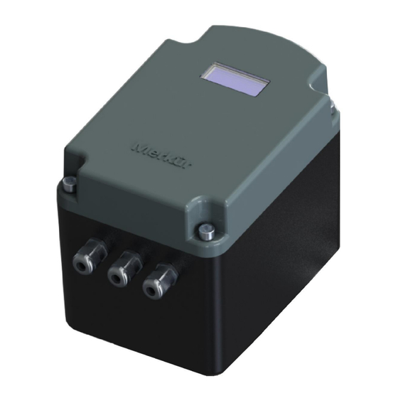
3 x PG9 waterproof plastic unions are supplied with SSM-6 motors, and can be found in the packing box. The cable entry holes to the motor are temporarily closed with a plastic plug. Do not remove the plugs unnecessarily! Always connect only the supplied PG9 unions to the cable entry points after removing the plugs! ... -
Page 13: Setup And Electrical Installation
: Connection clamp : Bottom switch block : 1.6 Amp. Fuse : Voltage input Figure 5 : Image of the PCB of SSM- Figure 4 : Program buttons of SSM-6 : Program Set Button MENU : Program Entry Button : Increase Button... -
Page 14: Introduction To The Electrical Connection Terminal
B - Introduction to the Electrical Connection Terminal As standard, SSM-6 motors are provided with a voltage of 24 VAC/DC. The supply voltage input is separate from the block clamps, as is seen in Figure 6. In motors with 24 VAC/DC input, the voltage input terminal block is BLUE. -
Page 15: Standard Electrical Connection
SSM-6 STANDARD ELECTRICAL CONNECTION (For All Functions) Figure 7 : General electrical connection for SSM-6 Motors 1 - Internal Connection 10 - Digital Output 1 NA Contact 2 - Internal Connection 11 - Digital Output 2 NA Contact 3 - TPSC input left turn... -
Page 16: Electrical Installation, Points To Consider
The voltage input terminal of the SSM-6 motors operating at 24 Volts is Blue colored. See Figure 8 The inputs of terminals 17 and 18 are live end (L+) and (N-) respectively. -
Page 17: Operation System Of Motors: On - Off Operating
Operating system of SSM-6 motors: - ON/OFF - TPSC – ANALOG - MODBUS - ON/OFF OPERATING SYSTEM : Aside from the constant power supplied to the servo motor, the motor moves in the direction of the ON position, towards the far end of the ON position angle, as long as power is supplied from the control input. -
Page 18: Tpsc Operation (Floating Control)
A TPSC (Three Position Step Control or Floating Control) operates between the maximum and minimum limits, based on the signal coming from the Digital inputs of the SSM-6 Servo motor. The electrical and control connections must be made as shown in Figure 10. The supply voltage enters from terminals 17 and 18. -
Page 19: Selectable Functions For On-Off And Tpsc - Password Entry
The standard password entry in all models of Merkür motors is as in Figure 11. You must know your login password in order to enter the password settings menu. The default password on SSM-6 servo motors is 1 2 3 4. You should follow the procedure in Figure 11 to enter the password. -
Page 20: How To Use The Standard Password Menu
How to use the standard password menu; 1 - Press the MENU button: the -MENU SETTINGS- message will be displayed on the screen 2 - Press the SET button: the PASSWORD message will be displayed and password digits will flash on the screen. -
Page 21: Menu For Changing Motor Direction
b - ) Changing the Direction of the Motor : Merkür Servo Motors are typically programmed to run CCW at the factory, rotating in a counter clockwise direction when observed from the shaft. If desired, you can change the direction of motor rotation from the menu shown in Figure 13 after entering your password. -
Page 22: Minimum And Maximum Angle Settings
- ) Minimum and Maximum Angle Settings : The angle of the SSM-6 Motors can be set within a range of 0° to 90° WARNING according to the requirement of the process. In SSM-6 motors, you can adjust the rotation angle within a range of 0° to 90°, starting from any angle above 0°... -
Page 23: Menu For Programmable Ignition Output
Figure 16 if the contact output function is to be used. Do apply loads up above the specified current so as not to damage the main board of the SSM-6. Strengthen the outputs with a second relay. Contact Output Connection... -
Page 24: Menu For Error Assignment To Contacts
-) Error Assignment Menu : If desired, you can program the programmable contacts for any of the following error messages. When an error code that you have assigned to the program occurs, the DO1 and DO2 relays check out. SSM-6 Motors equipped with programmable independent relays. -
Page 25: Retrospective Error Menu
No password is required to enter the error monitoring menu. You can learn the last 10 temporary or permanent errors related to the SSM-6 servo motor by following the menu shown in Figure 19. In this way you can obtain basic statistical data. -
Page 26: Menu For Manual Operation Of Motors
Be sure to return to the main screen after completing your manual operation! The SSM-6 motor will remain in the manual position unless manual mode is exited. When the SSM-6 is operating in manual mode, S indicates the set value and M indicates the value of the angle of the motor at that... -
Page 27: Analog Operation System And Bottom Switch Settings
Figure 21 : Analog Electrical Connection in SSM-6 Motors Analog inputs in SSM-6 Motors are as follows. If no analog input or output values are specified by the customer in the purchase order, SSM-6 Servo Motors are programmed, at the factory, to input and output values of 4-20 mA (It is a factor if there is output analog module). -
Page 28: Analog Operation And Output Curves - Analog Output Setting
0° to 90°. Example: If the Min. Angle of the SSM-6 is set to 20°, the analog output signal is 20° = X mA. Figure 24 shows the standard feedback curve of an SSM-6 Motor with an output signal set at FULL. -
Page 29: Analog Output Limitation Menu Of The Motor - Analog Configuration
Volt can be set to mA for output. To change the input or output type of the SSM-6 motor, the motor should first be deenergized, and then the position of the bottom switches should be changed for the desired control. (See Figures 22 and 23 for bottom switch positions) Afterwards, the analog operating system of the SSM-6 can be changed following the “ANALOG CONFIGURATION”... -
Page 30: Analog Input Change Menu - Analog Input Menu
4-20 mA when it is desired to be used differently. The input type in existing motors with an analog input can be easily changed, as shown in Figure 27. To change the input type, the supply voltage to the SSM-6 should first be cut off, CAUTION... -
Page 31: Analog Input Change Menu - Analog Output Menu
If your motor has an analog output module, you can change the output type as shown in Figure 28. Please pay attention to the Warning Notices! In SSM-6 servo motors, the analog output type is active if an output module is WARNING selected in the purchase order. -
Page 32: Analog Filter Time Setting Menu
In SSM-6 Motors, the filter time can be set, when required, to suit the analog input. The response time can be set from 0 to 5 seconds to avoid sudden changes in signal fluctuations or interferences. -
Page 33: Modbus Operating System
The Modbus Operating system is the standard communication protocol for the provision of data transfer and information exchange, as a means of meeting the communication needs of the industrial area. The SSM-6 servomotor must be parametrically set when it is desired to operate via the Modbus protocol. Modbus settings: ... -
Page 34: Sample Modbus Connection
Figure 32 : Modbus communication connection CAUTION 1 to 31 SSM-6 servo motors can be controlled via a Modbus connection. The communication connection should be made as shown in Figure 32. A 120 Ohm termination resistor must be used on the final motor to be used. The cables to be connected to terminals 12-13... -
Page 35: Modbus Communication Speed Selection
Modbus communication speed selection: Figure 33 : Communication speed selection If SSM-6 Servo Motors are selected with a Modbus communication in the purchase order, you can select the desired communication speed through the method shown in Figure 33. Communication speeds can be 2400, 9600 or 19200. After saving the selected communication speed by pressing the SET button, you can return to the main screen by pressing either the MENU button three times or the “BACK”... -
Page 36: Modbus Address Menu - Tablet And Mobile Phone Address Menu
Figure 35 : Address assignment menu via android phone or tablet If the operation via Bluetooth function is selected in the purchase order of an SSM-6 motor, the Hand Terminal can be activated through the menu shown in Figure 36, and the servo motors can... -
Page 37: Hand Terminal Access Menu
Hand terminal access menu: To pair the Android tablet or phone with the SSM-6 for remote control, the menu in Figure 36 should be used. In this way, the addressing process from the DV.ID block can be simplified via Bluetooth. -
Page 38: First Start-Up For Ssm
First start-up for SSM-6 servo motors: It is imperative that you check the installation before the initial start-up! WARNING • After making the necessary electrical connections, check that the sealing gasket on the inner side of the motor top cover is in-situ and proper! •... -
Page 39: Explanation Of Function Menus
Merkür Explanation of Function Menus in MERCURE Motors : MENU Settings menu containing motor information as per the engineering aspect -SETTINGS- MENU Respective error display menu during motor operation -HISTORY- PASWORD Security password provided to the user (Default password: 1 2 3 4 ) X X X X SETTIN Rotation direction, selecting the direction of motor rotation... -
Page 40: Explanation Of Function Menus
Merkür -COM.SET- Modbus communication speed: Communication speed setting between PLC and motor for Bluetooth-enabled SSM-6. (Modbus Baud) MB BAUD -MB BAUD- Communication speed 2400 Baud 2400 -MB BAUD- Communication speed 9600 Baud 9600 -MB BAUD- Communication speed 19200 Baud 19200 -COM.SET-... -
Page 41: Explanation Of Function Menus
- DO1.FUN- Limit Switch OFF (Motor full OFF) Input Alarm (In the case of an interruption of the input signal in the - DO1.FUN- analog-operated SSM-6 motors, the motor rotates in the OFF direction and generates contact output. INP.ALM - DO1.FUN- Low limit setting (The motor is running below the minimum limit value (0°). -
Page 42: Explanation Of Function Menus
Merkür - AI.TYP- Control Input Type (Analog Input) 0 -20 mA. 0 - 20 mA - AI. TYP- Control Input Type (Analog Input) 0 -10 mA. 0 - 10 V. - AI.TYP- Control Input Type (Analog Input) 2 -10 mA. 2 - 10 V. -
Page 43: Explanation Of Function Menus
Merkür - AO.RAN - 0 ° to 90 ° analog output range of the motor regardless of the set value Example: If the minimum value is set to 20°, the analog output 20º= 4mA. FULL - SETTIN - Digital Output Configuration DO.FUNCT - DO.CON - 1. -
Page 44: Explanation Of Function Menus
Merkür - CALIBR - Manual Operation; Function menu for operation of SSM-6 independent from input between 0 ° to 90 °, regardless of input signal MANUAL - MANUAL- S in Manual Position: Set angle value M: Position of the angle that motor is moving towards. -
Page 45: Menu Of All Functions
Merkür All function settings of SSM-6 PASSWORD Password entry (ROT.DIR) Direction of rotation of the motor (COMM.SET) Communication set Hand Terminal Authorization Modbus communication (DO.FUNCT) Digital Output Function = Limit Switch ON = Limit Switch Off P.LL.ALM = Low lower limit error P.HH.ALM = High higher limit error... -
Page 46: Menu Of All Functions
Merkür DI1.DEG = Dijital Input 1 DI2.DEG = Dijital Input 2 (MAIN CONF) Variable signal configuration AI CON : Analog Input Configuration AI FILT: Analog Input Filter AO.CONF: Analog Output Configuration AO.RANGE: Analog Output Settings (DO.CONFI) Analog output configuration Dry contact output setting at desired angle value CALIBRAT) Angle settings MIN.DEG : Minimum angle value... - Page 47 Merkür Merkür SSM–6 Wireless control and setting features Merkür is a Trademark of Era LTD.
Need help?
Do you have a question about the SSM-6 and is the answer not in the manual?
Questions and answers