Advertisement
Quick Links
Advertisement

Subscribe to Our Youtube Channel
Summary of Contents for Lincoln blum AVENTOS
- Page 1 AVENTOS Lift Systems Including SERVO-DRIVE for AVENTOS...
- Page 2 So fascinating SERVO-DRIVE BLUMOTION inside inside...
-
Page 3: Table Of Contents
New effortless opening and closing for lift systems Lift systems open with just a light touch - and then close again with the press of a button. The new electrical motion support system, SERVO-DRIVE for AVENTOS, can be used with or without handles. Discover for yourself how easy the opening and closing of lift systems can be, along with the function and design opportunities available to you with... - Page 4 So user-friendly The complete focus is on the kitchen user Completely safe even when closing Even when the switch has just been pressed for closing – the closing procedure is halted immediately if the kitchen user again reaches into the cabinet and/or an object is placed between the cabinet and the front.
- Page 5 Completely under control Even though lift systems open and close automatically: the kitchen user can interrupt the motion at any time. In addition, lift systems with SERVO-DRIVE for AVENTOS can also be easily opened and closed manually at any time, e.g. when there is a power failure. Once the power has been restored, SERVO- DRIVE for AVENTOS is again functional - no resetting is required.
- Page 6 So well co-ordinated with each other...
- Page 7 SERVO-DRIVE - the individual components After lift mechanism installation and adjustment, SERVO-DRIVE components are attached to the lift mechanism and cabinet. Lift mechanism Distance bumper » SERVO-DRIVE-compatible lift » Existing SERVO-DRIVE bumpers ensure mechanism with elongated hole for tool- the required trigger path free attachment to the drive unit of 2mm Cabling...
- Page 8 So practical Complete SERVO-DRIVE kitchens - one system for the entire kitchen With SERVO-DRIVE, you will experience trouble free opening throughout the entire kitchen. Whether it’s the base or wall cabinet – a single system automatically opens pull-outs & lift systems with the slightest touch.
- Page 10 So practical...
- Page 12 So easy Assembly – practically tool-free Most components can be attached tool-free, e.g. the drive unit, distance bumper or SERVO-DRIVE switch.
- Page 13 From assembly through to start-up Cabling – quick and easy Switch installation – fast & simple The piercing technology makes cabling very The SERVO-DRIVE switch is attached to the easy. A few steps is all that’s required to make cabinet side. Installation is very quick, simply the electrical connections.
-
Page 14: Frequently Asked Questions
So quickly answered Frequently asked questions How is this different from the regular Can I synchronise drive units? AVENTOS lift mechanism? Yes. Up to three drive units can be set so For the SERVO-DRIVE-compatible version, that they move simultaneously. the lift mechanism has an additional elongated hole in which the drive unit can Can I use asymmetrical fronts or fronts be inserted or clipped on during assembly. - Page 15 Where are the SERVO-DRIVE switches Can SERVO-DRIVE for AVENTOS be located? deactivated? The SERVO-DRIVE switches are attached Your customers can easily deactivate to the cabinet sides at the bottom. This SERVO-DRIVE for AVENTOS, e.g. to clean makes them easy to reach for thekitchen the fronts.
-
Page 16: Aventos Hf
AVENTOS HF Standard AVENTOS SERVO-DRIVE for AVENTOS... - Page 17 Lift mechanism Drive unit The drive unit is attached tool-free to the left lift mechanism. The same Telescopic arm drive unit can be used for all lift mechanisms. SERVO-DRIVE cover cap left Distribution cable The left cover cap is used to cover This cable is used to supply power the lift mechanism, drive unit and to the drive unit.
- Page 18 AVENTOS HF order specifications Wooden fronts and wide aluminium frames symmetrical/asymmetrical 3 types of lift mechanisms are enough to cover a wide range of applications. Using the power factor, you can calculate which mechanisms you require. The power factor required depends on the combined weight of the two fronts (including the handle weight)
- Page 19 SERVO-DRIVE cover cap set Opening angle stop Nylon, dark grey Light grey 21F8000 1-321-010 104° 20F7051 1-320-104 White 21F8000-W 1-321-012 83° 20F7011 1-320-083 Composed of: 1 x SERVO-DRIVE cover cap left Blum transformer 1 x cover cap right 2 x round cover caps 2 x SERVO-DRIVE switches Z10NE050.01 1-244-050...
- Page 20 AVENTOS HF planning information Wooden fronts and wide aluminium frames symmetrical Space requirement Drilling position for lift mechanism and distribution cable Ø 4 x 35 mm Cabinet height Only on the left side Drilling depth 5 mm Alternative drilling Cabinet height 480 - 549 mm KH x 0.3 - 28 mm 550 - 1040 mm...
- Page 21 Screw-on INSERTA / Knock-in / EXPANDO assembly Space requirement OEB = Opening angle stop Without OEB Y = FH x 0.44 + 38 OEB 104° Y = FH x 0.24 + 34 OEB 83° Y = 0 SERVO-DRIVE switch Blum distance bumper drilling position Blum distance bumper From cabinet front edge for fronts that protrude below Recommendation for aluminium frames:...
- Page 22 AVENTOS HF planning information Wooden fronts and wide aluminium frames asymmetrical Space requirement Drilling position for lift mechanism and distribution cable Ø 4 x 35 mm Theoretical cabinet height Only on the left side Cabinet height Drilling depth 5 mm Upper front height Alternative drilling Lower front height...
- Page 23 Screw-on INSERTA / Knock-in / EXPANDO assembly Space requirement OEB = Opening angle stop Without OEB Y = FH x 0.44 + 38 OEB 104° Y = FH x 0.24 + 34 OEB 83° Y = 0 SERVO-DRIVE switch Blum distance bumper drilling position Blum distance bumper From cabinet front edge for fronts that protrude below Recommendation for aluminium frames:...
-
Page 24: Aventos Hs
AVENTOS HS Standard AVENTOS SERVO-DRIVE for AVENTOS... - Page 25 Lift mechanism Front fixing bracket SERVO-DRIVE lever arm Cross stabiliser rod round Stabiliser adapter (steel) Drive unit The drive unit is attached tool-free to the left lift mechanism. The same Cross stabiliser cover cap drive unit can be used for all lift mechanisms.
- Page 26 AVENTOS HS order specifications Lift mechanism set for SERVO-DRIVE Cabinet height 350 - 525 Cabinet height 526 - 675 Cabinet height 676 - 800 20S2A00.05 1-321-110 20S2D00.05 1-321-116 20S2G00.05 1-321-122 20S2B00.05 1-321-112 20S2E00.05 1-321-118 20S2H00.05 1-321-124 20S2C00.05 1-321-114 20S2F00.05 1-321-120 20S2I00.05 1-321-126 Composed of:...
- Page 27 Front fixing bracket set Blum transformer Nickel plated Wooden fronts and wide alu frames 20S4200 1-320-130 Z10NE050.01 1-244-050 Composed of: 2 x symmetrical front fixing brackets SERVO-DRIVE connecting piece for cross stabiliser set Transformer unit housing for panel fixing Alu, Ø 16 mm, cabinet width 1219 mm and higher 21Q126Z 1-321-136...
- Page 28 AVENTOS HS order specifications The cabinet front and door weight is required in order to select the correct lift mechanism. Example: Cabinet height KH = 600 mm Weight of front = 10 kg Lift mechanism selection = 1-321-118 20S2E00.05 Cabinet height KH = 602 mm rounded to KH = 600 mm Cabinet height KH = 603 mm rounded to KH = 605 mm Door weight (kg) Door weight (kg)
- Page 29 Door weight (kg) 1-321-110 1-321-112 1-321-114 KH (mm) 20S2A00.05 20S2B00.05 20S2C00.05 2.50 - 4.00 3.25 - 7.50 7.25 - 15.00 2.50 - 4.00 3.50 - 7.50 7.25 - 15.00 2.50 - 4.00 3.50 - 7.50 7.25 - 14.75 2.50 - 4.00 3.50 - 7.75 7.50 - 14.75 2.50 - 4.00...
- Page 30 AVENTOS HS planning information Space requirement Drilling position for lift mechanism and distribution cable Ø 4 x 35 mm Only on the left side Drilling depth 5 mm Alternative drilling Top panel thickness Front assembly Wooden fronts and wide alu frames Upper front overlay Side front overlay If cabinet is mounted against wall on left/right,...
- Page 31 Front setting Cornice and crown moulding clearance Cross stabiliser [1] KB (KS 16 - 19 mm ) -193 mm and/or inner width -155 mm Connecting piece Dimensions depend on tilt adjustment Gap F X max Y max 3 mm 35 mm 101 mm [2] half KB (KS 16 - 19 mm) -193 mm 2 mm...
-
Page 32: Aventos Hl
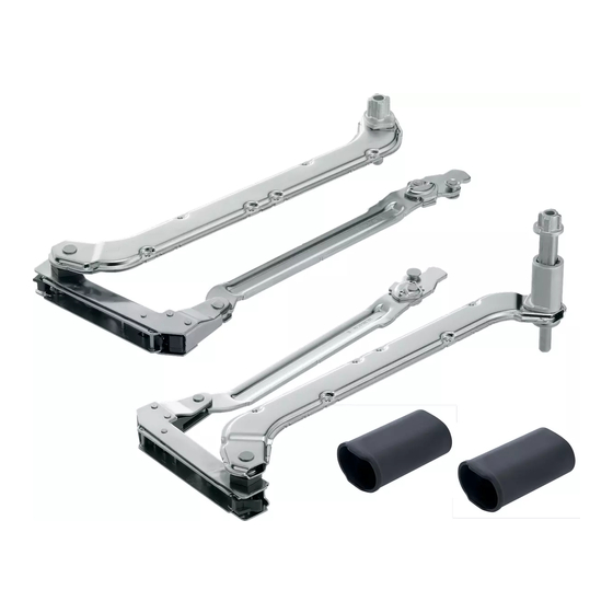
AVENTOS HL Standard AVENTOS SERVO-DRIVE for AVENTOS... - Page 33 Lift mechanism Front fixing bracket SERVO-DRIVE lever arm Oval cross stabiliser Lever arm right Drive unit The drive unit is attached tool-free to the left lift mechanism. The same Stabiliser adapter (steel) drive unit can be used for all lift mechanisms.
- Page 34 AVENTOS HL order specifications 5 types of lift mechanisms are enough to cover a wide range of applications. The cabinet front and door weight is required in order to select the correct lift mechanism. Cabinet height Lever arm Lift mechanism 20L2100.05 1-321-150 20L2300.05...
- Page 35 Standard lever arm set Cross stabiliser rod oval Nickel plated steel 20L2200 1-320-160 Cabinet height 300 - 349 mm For cutting to size, 1061 mm 20Q1061UA 1-320-170 20L2500 1-320-162 Cabinet height 350 - 399 mm Cabinet height 400 - 550 mm 20L2800 1-320-164 SERVO-DRIVE set...
- Page 36 AVENTOS HL planning information Space requirement Drilling position for lift mechanism and distribution cable Ø 4 x 35 mm Lever arm min LH (mm)* Y (mm)* Internal cabinet height Only on the left side 21L3200 KH Cabinet height Drilling depth 5 mm 21L3500 Alternative drilling 21L3800...
- Page 37 Front setting Cornice and crown moulding clearance Cross stabiliser [1] KB (KS 16 - 19 mm ) -193 mm and/or inner width -155 mm Connecting piece Lever arm a (mm)* b (mm)* SOB (mm) X (mm) 21L3200 21L3500 21L3800 [2] half KB (KS 16 - 19 mm) -193 mm 21L3900 Cabinet width Cabinet thickness...
-
Page 38: Servo-Drive For Aventos Assembly
SERVO-DRIVE for AVENTOS assembly Drive unit adjustment Before SERVO-DRIVE for AVENTOS installation, the lift mechanisms must be adjusted so that the fronts stay in any given position without opening or closing of their own accord. The AVENTOS lever arm must be in the completely open position for drive unit installation. - Page 39 Drive unit lock SERVO-DRIVE switch installation Blum distance bumper assembly Do not glue the Blum distance bumper. Aluminium frame: NOTE: Hole is 5mm diameter and 10mm deep Installation in the front Installation in the cabinet side...
- Page 40 SERVO-DRIVE for AVENTOS assembly Blum transformer and accessories Space requirement and safety distance for Blum transformer unit housing A safety distance of 30 mm must be maintained for air circulation (see graphic); otherwise, there is a risk that the Blum transformer could overheat. Assembly in combination with Assembly on the top panel SERVO-DRIVE for pull-out systems...
- Page 41 Cable diagram for two cabinets Assembly in combination with SERVO-DRIVE for pull-out systems Transformer unit housing Pull-out stop Distribution cable for cutting to size Connecting node Cable end protector Do not damage piercing pins Blum transformer Transformer unit housing Flex Only one Blum transformer can be connected to each distribution cable.
- Page 42 Overview of functions for SERVO-DRIVE for AVENTOS Start-up Activating the SERVO-DRIVE switch Additional features Activating synchronisation Activating collision avoidance Start reference run Deactivation Reset motion Reset wireless Button layout Drive unit <Reset Motion> button Motion LED <SWITCH> button <SYNC> button <COLL>...
- Page 43 SERVO-DRIVE for AVENTOS start-up Operation Lights up continuously Flashes Activating the SERVO-DRIVE switch Setting up the wireless connection between the SERVO-DRIVE switch and the drive unit. Each switch can only be assigned to one SERVO-DRIVE unit. Press the <SWITCH> button Press the SERVO-DRIVE until the LED flashes switch until the LED lights up...
- Page 44 SERVO-DRIVE for AVENTOS additional features Activating synchronisation Up to three drive units can be synchronised allowing them to move simultaneously. This function is required for several cabinets with a uniform front. Press the <SYNC> button Press <SYNC> on the 2nd on the 1st drive unit until the drive unit until the LEDs on both LED flashes...
- Page 45 Deactivating SERVO-DRIVE for AVENTOS Flashes quickly Reset motion Resets the reference run and enables a new reference run to be started. Press the <Reset Motion> button using a pen (at least 3 seconds) until the LED flashes quickly. Reset wireless Deactivates all functions.
-
Page 46: Cover Cap Assembly And Battery Replacement
Cover cap assembly and battery replacement Cover cap Battery replacement » Only use type CR2032 batteries from known manufacturers. » Make sure that the new battery is inserted correctly (note proper pole connections +/-). » The SERVO-DRIVE switch battery must not be recharged or thrown into fire. - Page 47 Removal Drive unit removal DANGER » Before starting repair or maintenance work, unplug the Blum transformer to disconnect the power. » Never open a Blum transformer. There is a danger of electric shock. Removal of Blum transformer and accessories Do not damage piercing pins...
- Page 48 Call your nearest branch on: Western Australia Queensland South Australia Malaga Lonsdale Ph: 1300 55 19 19 Brisbane Bunbury Woodville Bundaberg Fax: 1300 739 656 Cairns Tasmania Victoria Gold Coast Launceston Australian Capital Territory Bayswater Hobart Mackay Canberra Thomastown www.lincolngroup.com.au Northgate Dandenong Northern Territory...
Need help?
Do you have a question about the blum AVENTOS and is the answer not in the manual?
Questions and answers