
Subscribe to Our Youtube Channel
Summary of Contents for CTI-CRYOGENICS On-Board Network Terminal
- Page 1 CRYOGENICS HELIX TECHNOLOGY CORPORATION Network Terminal Installation, Operation, and Maintenance Instructions 8040375G001 Rev. 100 (11/2001) HELIX TECHNOLOGY CORPORATION http://www.helixtechnology.com...
- Page 2 The following Helix Technology Corporation trademarks and service marks may appear in this document: Conductron™ ® ® ® Convectron Cryodyne Cryogen ® ® ® FastRegen™ Cryogenerator Cryo-Torr CTI-Cryogenics ® Granville-Phillips™ ® Helix Technology.. Your GOLDLink GUTS Vacuum Connection ® ® Mini-Ion™ ® Helix Micro-Ion On-Board ®...
- Page 3 CRYOGENICS HELIX TECHNOLOGY CORPORATION Software License Agreement This software license agreement (“Agreement”) grants you the right to use the software contained in this product (the “Software”) subject to the following restrictions. You may not (i) copy the Software, except for archive purposes consistent with your standard archive procedures; (ii) transfer the Software to a third party apart from the entire product;...
-
Page 4: Table Of Contents
CRYOGENICS Network Terminal Installation, Operation, and Maintenance Instructions HELIX TECHNOLOGY CORPORATION Table of Contents Section 1 - Introduction General ............1-1 On-Board NetLink Option . - Page 5 CRYOGENICS Network Terminal Installation, Operation, and Service HELIX TECHNOLOGY CORPORATION Table of Contents (continued) Establishing Roughing Maps and Password Protection ..... 4-4 Full Rough Coordination Functionality .
- Page 6 Table 6-1:Network Terminal Failure Messages ......6-2 Table A-1:CTI-CRYOGENICS Product Customer Support Centers ..A-2 Table B-1:Result Codes .
-
Page 7: Section 1 - Introduction
Network Terminals. NOTE: The Network Terminal must either have the communication ports or be upgraded to communicate with the On-Board NetLink. Refer to the On-Board NetLink Installation, Operation, and Maintenance manual CTI-CRYOGENICS P/N 8040390 for more information. P/N 8040375G001... -
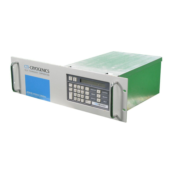
Page 8: Figure 1-1: Network Terminal Configurations
CRYOGENICS Introduction HELIX TECHNOLOGY CORPORATION Half Panel Full Panel Rear View (Half and Full Panel) Figure 1-1: Network Terminal Configurations P/N 8040375G001... -
Page 9: Specifications
CRYOGENICS Network Terminal Installation, Operation, and Maintenance Instructions HELIX TECHNOLOGY CORPORATION Specifications Refer to Table 1-1 and Figures 1-2 and 1-3 for the specifications and dimensions of the half and right hand panel Network Terminal configurations. Table 1-1: Network Terminal General Specifications Parameter Value Weight... -
Page 10: Figure 1-2: Half Panel Dimensions
CRYOGENICS Introduction HELIX TECHNOLOGY CORPORATION Figure 1-2: Half Panel Dimensions P/N 8040375G001... -
Page 11: Figure 1-3: Network Terminal Right Hand Configuration
CRYOGENICS Network Terminal Installation, Operation, and Maintenance Instructions HELIX TECHNOLOGY CORPORATION Figure 1-3: Network Terminal Right Hand Configuration P/N 8040375G001... -
Page 12: Front Panel Component Description
CRYOGENICS Introduction HELIX TECHNOLOGY CORPORATION Front Panel Component Description Keypad/Display Control Description The On-Board keypad/display, shown in Figure 1-4, provides a user interface to the Network Terminal for programming and operating all On- Board Pump functions. Figure 1-4 shows the location of all function keys and the alphanumeric display. -
Page 13: Clear Display Key
The function keys allow the user to select the software function in which programming or operation is desired. Service RS-232 Port The Service RS-232 port allows you, or a CTI-CRYOGENICS Field Service Representative, to connect the RS-232 port of a portable computer to the Network Terminal for communication purposes. The port is mounted on the front panel for easy access and supports baud rates of 2400, 9600, and 19200. -
Page 14: Led Indicator
The Network Connectors are used to connect an On-Board NetLink and other Network Terminals when multiple On-Board networks are required. Refer to the On-Board NetLink Installation, Operation, and Maintenance manual CTI-CRYOGENICS P/N 8040390 for more information. Address Switch The Address Switch allows you to select the network address of the Network Terminal that is connected to the On-Board NetLink. -
Page 15: Figure 1-5: Example Of Daisy Chained Pump Configuration
CRYOGENICS Network Terminal Installation, Operation, and Maintenance Instructions HELIX TECHNOLOGY CORPORATION EMI Bonding Stud Terminator Terminator Figure 1-5: Example of Daisy Chained Pump Configuration P/N 8040375G001... -
Page 16: Section 2 - Inspection
CRYOGENICS Network Terminal Installation, Operation, and Maintenance Instructions HELIX TECHNOLOGY CORPORATION Section 2 - Inspection General On receipt, inspect the Network Terminal for evidence of damage. Report any damage to the shipping company at once. Retain the shipping cartons for storage or return shipment. Inspect the Network Terminal for damage by examining the overall exterior, keypad, electrical connectors, ON/OFF switch, and the power cable for damage. -
Page 17: Section 3 - Installation
Network Configurations As many as twenty On-Board Cryopumps can be connected to the Network Terminal. The pumps are networked together using CTI-CRYOGENICS network cables. Before connecting the pumps together, set the address switch on each pump so that each pump has its own number from 0-9. -
Page 18: Figure 3-1: Example Of Daisy Chained Pump Configuration
CRYOGENICS Installation HELIX TECHNOLOGY CORPORATION EMI Bonding Stud Terminator Terminator Figure 3-1: Example of Daisy Chained Pump Configuration P/N 8040375G001... -
Page 19: Power Connections
CRYOGENICS Network Terminal Installation, Operation, and Maintenance Instructions HELIX TECHNOLOGY CORPORATION Cryopump Network Selector Switch Figure 3-2: Network Selector Switch Location Power Connections The Network Terminal is shipped from the factory set to the 110/120 VAC setting. The input power connector will have to be modified if you plan to operate the Network Terminal at 220/240 VAC. -
Page 20: 220/240 Vac
CRYOGENICS Installation HELIX TECHNOLOGY CORPORATION 220/240 VAC 1. Modify the input power connector as follows: a. Place a small flat head screwdriver in the slot above the lettering and twist out the fuse holder module as shown in Figure 3-3. Insert Screwdriver Blade Here USE ONLY WITH 250V... - Page 21 CRYOGENICS Network Terminal Installation, Operation, and Maintenance Instructions HELIX TECHNOLOGY CORPORATION NOTE: The bonding stud, as shown in Figure 3-1, is intended for applications where Electromagnetic Interference (EMI) may be a problem. It is not to be used as a protective ground. Attach a ground using accepted EMI grounding practices.
-
Page 22: Section 4 - Operation
CRYOGENICS Network Terminal Installation, Operation, and Maintenance Instructions HELIX TECHNOLOGY CORPORATION Section 4 - Operation Addressing a Pump To address any pump on the network, refer to Figure 4-1 and perform the following steps: 1. Press the function key for the desired function (i.e., MONITOR, REGEN, etc.). -
Page 23: Roughing Maps
CRYOGENICS Operation HELIX TECHNOLOGY CORPORATION Roughing Maps For multi-pump systems that share a roughing pump through a roughing manifold, it is necessary to map the Cryopumps as shown in Figure 4-2. A roughing map keeps track of which pumps are on which roughing manifold. -
Page 24: Rough Valve Map Example Procedure
CRYOGENICS Network Terminal Installation, Operation, and Maintenance Instructions HELIX TECHNOLOGY CORPORATION Rough Valve Map Example Procedure Use the following procedure to create a rough valve map as shown in Figure 4-2. NOTE: A minimum of 2 pumps per map is required. 1. -
Page 25: Establishing Roughing Maps And Password Protection
CRYOGENICS Operation HELIX TECHNOLOGY CORPORATION Once a Cryopump which is contained within a roughing map has started FastRegen, no other Cryopump in that map can start a FastRegen until that pump reaches 115K in cooldown. Full regenerations can be started individually or in groups at any time. -
Page 26: Full Rough Coordination Functionality
CRYOGENICS Network Terminal Installation, Operation, and Maintenance Instructions HELIX TECHNOLOGY CORPORATION 12. Enter the next number for that map, etc. 13. When all of the pump numbers have been entered, press Enter one more time and MAP A will be stored and the display will then read MAP B and display all of the pumps in that map. -
Page 27: Power Fail Coordination Functionality
CRYOGENICS Operation HELIX TECHNOLOGY CORPORATION 7. Press Next. The display reads OFF FULL COORDINATION. 8. Press 1 to turn Full Rough Coordination feature ON. Press 0 to turn it OFF. Power Fail Coordination Functionality NOTE: This feature only exists in some custom Network Terminals and may not be available in the Network Terminal you are operating. -
Page 28: Setting Up Regeneration Groups With The Network Terminal
CRYOGENICS Network Terminal Installation, Operation, and Maintenance Instructions HELIX TECHNOLOGY CORPORATION Cryopump on a roughing manifold and they are to be put through a FastRegen, then they must all be started and run at the same time so that they can all be roughed at the same time. This also means that if there is a Cryopump in the process of FastRegen, then no other Cryopump on that roughing manifold can start a FastRegen until that Cryopump is finished. -
Page 29: Starting A Group Regeneration From The Network Terminal
CRYOGENICS Operation HELIX TECHNOLOGY CORPORATION Starting a Group Regeneration From the Network Terminal 1. Press REGEN 9 9. The display reads 1-MULTI PUMP RGN. The 1 indicates that group 1 is selected for regeneration. 2. Press 1 to start a regeneration. The display reads PRESS 2 OR 3 REGEN PUMPS?. -
Page 30: Setting The Rs-232 Port Baud Rates
CRYOGENICS Network Terminal Installation, Operation, and Maintenance Instructions HELIX TECHNOLOGY CORPORATION Setting the RS-232 Port Baud Rates 1. Press SERVICE 9 9 to access to the local Service function of the terminal. Press Next, then Next again to display the password prompt. -
Page 31: Section 5 - Maintenance
CRYOGENICS Network Terminal Installation, Operation, and Maintenance Instructions HELIX TECHNOLOGY CORPORATION Section 5 - Maintenance Memory Backup Battery The memory backup battery is the only part within the Network Terminal that you can maintain. This battery provides memory backup capabilities for items such as rough valve maps, multi-pump REGEN programs, and the unit serial number when AC power is removed from the Network Terminal. -
Page 32: Memory Backup Battery Replacement
CRYOGENICS Maintenance HELIX TECHNOLOGY CORPORATION 2. Remove the Network Terminal top cover by removing the two screws on the rear panel and lifting the cover from the rear of the chassis. 3. Refer to Figure 5-1 to locate the battery B1 and resistor R3 on the circuit board. -
Page 33: Figure 5-1: Memory Backup Battery (B1) And Resistor (R3) Locations
CRYOGENICS Network Terminal Installation, Operation, and Maintenance Instructions HELIX TECHNOLOGY CORPORATION Front Resistor (R3) Battery (B1) Place Positive (+) Meter Probe Here. Place Negative (-) Meter Probe Here. Figure 5-1: Memory Backup Battery (B1) and Resistor (R3) Locations P/N 8040375G001... -
Page 34: Section 6 - Troubleshooting
CRYOGENICS Network Terminal Installation, Operation, and Maintenance Instructions HELIX TECHNOLOGY CORPORATION Section 6 - Troubleshooting If You Have Problems Starting A Group FastRegen If you attempt to start a Group FastRegen and GROUP REGEN ERR is displayed on the Network Terminal keypad/display, it means that the pumps were not started into regeneration for one of the following reasons: 1. -
Page 35: Network Terminal Failure Messages
CRYOGENICS Troubleshooting HELIX TECHNOLOGY CORPORATION Network Terminal Failure Messages Table 6-1: Network Terminal Failure Messages Message Possible Problem Session Lost Communication was lost to that pump. Line break or noise. Session Failed A session was attempting to open and there was a line break or noise. -
Page 36: Appendix A - Customer Support Information
Introduction Refer to Table A-1 for the nearest Customer Support Center for technical assistance or service for CTI-CRYOGENICS products. North American customers may call 800-FOR-GUTS (800-367-4887) 24 hours a day, seven days a week. All other customers must call their local Customer Support Center. -
Page 37: Table A-1:Cti-Cryogenics Product Customer Support Centers
CRYOGENICS Appendix A - Customer Support Information HELIX TECHNOLOGY CORPORATION Table A-1: CTI-CRYOGENICS Product Customer Support Centers United States and Canada Germany, Italy, Denmark, Switzerland, Holland, Norway, The Netherlands ® Guaranteed Uptime Support Line GUTS Dial: +(49) 6151-959-55 Dial: 800-FOR-GUTS (800-367-4887) (within USA) -
Page 38: Appendix B - Network Terminal Rs-232 Interface Protocol Format
CRYOGENICS Network Terminal Installation, Operation, and Maintenance Instructions HELIX TECHNOLOGY CORPORATION Appendix B - Network Terminal RS-232 Interface Protocol Format Introduction The format of RS-232 messages between a computer device (the HOST) and the Network Terminal (slave) is the same for both directions of message flow (HOST transmitted or slave transmitted). - Page 39 CRYOGENICS Appendix B - Network Terminal RS-232 Interface Protocol Format HELIX TECHNOLOGY CORPORATION it used to produce the data field, and appends it after the field just prior to the CR code terminator. The receiving unit performs the same checksum algorithm on all characters which it receives between the ’$’...
- Page 40 CRYOGENICS Network Terminal Installation, Operation, and Maintenance Instructions HELIX TECHNOLOGY CORPORATION field contents are not correct and cannot be interpreted. This is not a communications error, but a software error. Invalid commands, improper parameter ranges, or requests to perform operations which are disallowed for some reasons all result in an error message reply.
- Page 41 CRYOGENICS Appendix B - Network Terminal RS-232 Interface Protocol Format HELIX TECHNOLOGY CORPORATION The following is an example of a typical exchange: Host Sends query to get back On-Board Module Version Information for Pump #1 Pump Data Flag Checksum Terminator Address Field ASCII...
- Page 42 CRYOGENICS Network Terminal Installation, Operation, and Maintenance Instructions HELIX TECHNOLOGY CORPORATION Checksum of hex data field: Bits 76543210 Sum of 01000001 01010000 00100000 01000001 00110010 00101110 00110000 00110001 Equals 10110011 or hex B3 modulo 256. Bits 7 & 6 aligned for 00000010 X0R result 10110001 or B1.
-
Page 43: Figure B-1: Rs-232 Cable Connections
CRYOGENICS Appendix B - Network Terminal RS-232 Interface Protocol Format HELIX TECHNOLOGY CORPORATION IBM-PCxT On-Board Module 2 R x D <- <- T x D 2 3 T x D -> <- R x D 3 Shield 9 Pin Male GND 7 CAUTION The RS-232 cable should not... -
Page 44: Table B-1:Result Codes
CRYOGENICS Network Terminal Installation, Operation, and Maintenance Instructions HELIX TECHNOLOGY CORPORATION Result Codes All of the RS-232 ports support hardware and software busy signals. Use pin 8 of the RS-232 Connector for clear to send (CTS) hardware busy. Use hardware and XON and XOFF for software. Table B-1: Result Codes Letter Description... -
Page 45: Table B-2:Network Terminal Rs-232 Commands
CRYOGENICS Appendix B - Network Terminal RS-232 Interface Protocol Format HELIX TECHNOLOGY CORPORATION Table B-2: Network Terminal RS-232 Commands Command Parameter Description None Acknowledges that host computer is aware of a power reset state at the multiplexor, resetting the internal state which causes the ’A’... - Page 46 CRYOGENICS Network Terminal Installation, Operation, and Maintenance Instructions HELIX TECHNOLOGY CORPORATION Table B-2: Network Terminal RS-232 Commands (Continued) Command Parameter Description None Returns a numeric code that identifies which pump modules are currently active on the network. When this command is sent, the network multiplexor sends out a polling request to all pumps.
- Page 47 CRYOGENICS Appendix B - Network Terminal RS-232 Interface Protocol Format HELIX TECHNOLOGY CORPORATION Table B-2: Network Terminal RS-232 Commands (Continued) Command Parameter Description B (contin- None For example, a code of 0 indicates no pumps responding. A ued) code of 12 indicates pump 2 and pump 3 are responding. This notation is a compressed form of set notation.
- Page 48 CRYOGENICS Network Terminal Installation, Operation, and Maintenance Instructions HELIX TECHNOLOGY CORPORATION Table B-2: Network Terminal RS-232 Commands (Continued) Command Parameter Description None Returns a numeric code that identifies which pump modules are assigned to one of the five cooperative sets. This mem- bership is logically based on the programming of the five sets, and does not rely on whether the pumps are currently communicating or not.
- Page 49 CRYOGENICS Appendix B - Network Terminal RS-232 Interface Protocol Format HELIX TECHNOLOGY CORPORATION Table B-2: Network Terminal RS-232 Commands (Continued) Command Parameter Description Set Code 0 - 31 Command to acquire sets which are not already in coopera- Returns Set tive use.
- Page 50 CRYOGENICS Network Terminal Installation, Operation, and Maintenance Instructions HELIX TECHNOLOGY CORPORATION Table B-2: Network Terminal RS-232 Commands (Continued) Command Parameter Description [1-5] Accepts a numeric code that identifies which pump modules [0 - 1048575] are grouped in the selected gang start pump grouping. The parameter 1 through 5 selects the groups ’1’...
- Page 51 CRYOGENICS Appendix B - Network Terminal RS-232 Interface Protocol Format HELIX TECHNOLOGY CORPORATION Table B-2: Network Terminal RS-232 Commands (Continued) Command Parameter Description [0 - 1]? Command to disable competing RS-232 ports (1) or allow competing RS-232 ports (0, the default). When a serial port receives the g1 command, the remaining ports will be inhib- ited from future access to the Network Terminal or thepumps and will reply with either the I or J reply, indicating they are...
Need help?
Do you have a question about the On-Board Network Terminal and is the answer not in the manual?
Questions and answers