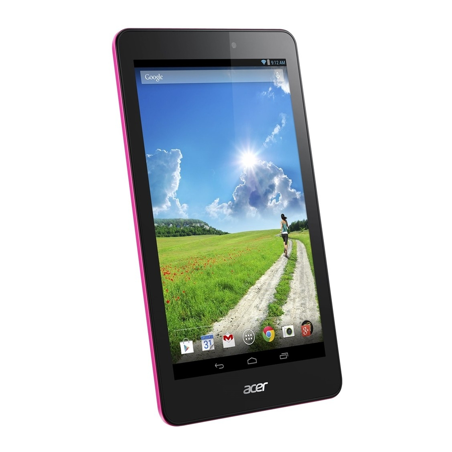
Page 3
Conventions The following conventions are used in this manual:...
Page 4
If, for whatever reason, a part number change is made, it will not be noticed in the printed Service Guide. For ACER-AUTHORIZED SERVICE PROVIDER, your Acer office may have a DIFFERENT part number code to those given in the FRU of this printed Service Guide.
Page 5
Overview Chapter 1: a. Product Features / HW Spec b. Product six view and description c. System block diagram Chapter 2: a. Software Upgrade SOP (SOP of SD Download and EUU) b. Service tool SOP Chapter 3: a. Disassembly and Assembly SOP b.
Page 6
Chapter 1: a. Product Features / HW Spec System Android Lollipop system 5.0 Operating System Image download mechanism and tools need to support Secure OS at production line for Widevine DRM Level 1 Processor Intel®Atom processor Z3735G (1.83 GHz, DDR3L 1333 MHz) ...
Page 7
802.11g: under -70dBm at 54Mbps 802.11n: under -67dBm at MCS 7 (2.4GHz only) Single antenna (without diversity) Antenna Support 2.4~2.5GHz band. Performance should meet test summary document released by Acer DQM. Bluetooth® 4.0 Module Broadcom BCM43438 MAC address Device must contain Bluetooth MAC address before shipment...
Page 8
720P H.264 video playback on system (720p 影片循環播放+螢幕亮度 : 100nits+耳機輸出+WLAN/3G 開啟+登入 Gmail 並更新。)) Youtube playback 720p video min. 5.75 hours via WIFI. Detailed criterion defined in the test summary document released by Acer DQM. Battery low: when battery capacity is 15 % ...
Page 9
Long press 1 second to show power-off dialog (when device is on even in lock state) Once CPU is on, system Acer logo should show up within 2 seconds. Press to suspend the device (when device is on) ...
Screen lock Shutdown hole Press to turn off the system LED Indication Connector Micro-USB 2.0, OTG Micro USB VID: 0502 Life cycle: Min. rating of 10K connect / disconnect cycles HDMI 3.5mm Audio Jack 4ring ( with Mic) ...
Page 11
Gyro-meter P-Sensor Certification Requirement should meet test summary document released by Acer DQM. CE / FCC / IC / NCC / CB / BSMI / BQB / WiFi / WHQL Certification Country List: Defined in the document “Citizen Country List”...
Chapter 2: a. Software Upgrade SOP Equipment: 1. PC with 32 bit XP/WIN7/WIN8 2. USB cable Install Driver & Tool : 1. Enter to fastboot mode Fast key enter to recovery mode Press “Power” and “Volume up” key together(over 3 sec) release “Power” key, but keep pressing the “volume up”...
Page 16
3. Connect PC and Android Tablet by USB cable 4. Install “Windows_adb_driver” in your PC. 5. When drivers install usefully, you can see below drawing in Devices Administrator in PC. Install Download Tool: 1. Install PhoneFlashTool_5.2.1.0_external_win32.exe in your PC, When set up in final, you may see the “Phone Flash Tool” icon in your program bar. Image : 1.
Page 17
Start to download: ( Factory image Shipping image; Shipping image Shipping image) 1. Enter to fastboot mode 2. Connect your Android Citizen with PC by USB cable, and click the “Phone Flash Tool” icon Phone Flash program will auto Popup on PC display You may see this linking information when Citizen connect to PC .
Page 18
PS. Don’t disturb or plug out the USB cable for instant, to avoid image broken within image download period. 4. When image download finish (as below 100% progress drawing), please push “power” key to make the tablet reboot. PUSH Download finish 5.
Page 19
Start to download: (Shipping image Factory image ) 1. Enter to fastboot mode by fast key, then connect PC by USB cable 2. Connect B1-820 with PC by USB cable, and click the “Phone Flash Tool” icon Phone Flash program will auto Popup on PC display Search the unzip image location by clicking icon “Browser”.
Page 20
4. When press “Power” key to reboot, show the display. Then need press “Power key” to reboot again 5. Long press “Power” key to power off, and enter to recovery mode. Then wipe all user data. 6. Reboot system, and download to factory mode process complet.
Page 21
SD card Install Download SOP 1. Put OTA image file on SD card 2. Fast key enter to recovery mode. Press “Power” and “Volume up” key together(over 3 sec) release “Power” key, but keep pressing the “volume up” key, until recovery mode display popup. 3.
All of the below Read/Rewrite action, need to install “IntelAndroidDriver” and “Factory image” in your (it’s unnecessary if your PC has installed) Following example will put adb tool under C folder Read Acer SNID 1. Switch on Citizen adb port 2. Connect Citizen and PC by USB cable 3.
Page 23
Then, have the write command as new Acer 22 code SN To power off Power on, then make new Acer 22 code SN effective. Read Acer Wifi Mac address 1. Ensure to switch on Wifi function on device...
Page 24
Double click “Citizen Wifi Mac read.bat” in c:\adb 4. You may also return to C:\adb folder to open “mac.txt” file in PC, and check the content as well. Re-write Acer Wifi Mac address Switch on Citizen adb port Connect Citizen and PC by USB cable To open “C:\adb”...
Page 25
Read Acer BT address 1. Switch on Citizen adb port 2. Connect Citizen and PC by USB cable 3. Double click “Citizen BT read.bat” in c:\adb You may also return to C:\adb folder to open “bd_addr.conf” file, and check the content as well.
Page 26
Double click “Citizen BT write.bat” in c:\adb Read country code The Wifi country code deification, as below a. 1: For shipping to US b. 0: For shipping to WW others non: For shipping to WW others. 1. Switch on Citizen adb port 2.
Page 27
Double click “Citizen country cod read write.bat” in c:\adb Log capture command 1. Switch on Citizen adb port 2. Connect Citizen and PC by USB cable 3. Double click “User log.bat” in c:\adb 4. Press “Ctrl” + “C” to clos log catching. 5.
Page 28
Chapter 3: Disassembly and Assembly SOP Disassembly: Disassembling tool Plastic stick 橇棒 (厚度 0.5~0.7mm) tweezers 小型鑷子 tweezers 十字起子(#0) Insert the plectrum into gap which next to the side key. 2. Hold the plastic stick and gash the gap, slide and separate the back cover base on the direction of clasp. (2 on left side, 4 on down side).
Page 29
Slide the plastic stick until the middle position of bottom and break open LCD cover by pressing down the plastic stick 3. Hold the cover and take off the cover base on the axis of LCD cover up side. 4. Take off the battery Tear off the tap on connector, and separate the battery connector, and pulling two side of battery sticker.
Page 30
5. Take off the main PCBA board Remove the screw and take off the speaker box, USB metal holder, and separate all connector, take off FPC and antenna board. After that you can separate the PCBA and other parts.
Page 31
6. Take off TP-LCM and LCD Bezel Put TP-LCM/ LCD bezel on oven under the degree of 70~80 centigrade, then separate the TP-LCM and LCD Bezel after around 20 min. 7. Finish. All parts disassembled drawing...
Page 32
Assembly: Step1. Tear off the liner paper, stick and fix LCM and LCD bezel Step2. To assemble side-key FPC on LCD Bezel...
Page 33
Step3. Stick Side key FPC on LCD Bezel, Put VGA Camera on LCD Bezel, Put ANT PCB on bezel and stick the Cu foil on metal frame Step 4 Put MIC Rubber on PCB MIC, and stick on PCBA Step 5. Assembly Metal USB with screw >> Fix the PCB on LCD Bezel >> Connect Side Key FPC with ZIF contr.
Page 34
Step6. Put Back Camera on LCD Bezel, and connect with ZIF contr.. Step7. Put TP board and stick on Metal Frame >> Connector TP FPC with ZIF contr. Step8. Put SPK BOX on LCD Bezel and fix it by screw >> Connect SPK BOX connector with TP board.
Page 35
Step9. Assemble LCM FPC with LCM module which on PCBA >> Stick Battery on bezel, and lock BTB connector. Step10. Put the tape (醋酸膠布)on each ZIF cntr. 及 WTB cntr...
Page 36
Step 11. Base on direction to assembly back cover, and make sure the well locking with device.
Page 37
Chapter 4: Diagnostic Tool SOP How to Enter in Hardware Testing Mode Press the MENU button, and click on ICON “Factory Test Tool”in APPS, press the button perform the functional test. Figure 1.1 Figure 1.2 Select Manual UI Testing as Hardware testing items Touch draw double frame...
Page 38
Draw Diagonal Rear Camera Blemish Front Camera Key Speaker SD Card Headset Mic Head set Mic G Sensor Verify Water Ripple 1 Water Ripple 2 Bluetooth G Sensor Backlight LCD TP Around Test Power Current Touch Calibration Uniformity Passive pen drawing...
Page 39
Hardware testing items Using Guide Backlight: Backlight test, show backlight Level30-Level130-Level230 successively, and then according to the actual result that you saw to choose “High Back Light” or “Low Back Light” , as shown below: This example may get PASS when you choose “Low Back Light” KEY: •...
Page 40
Front_Camera: Front Camera test, click on any position of display, it should take a picture by front camera, check the picture and according to the actual result that you saw to choose PASS or FAIL. Rear_Camera: Rear Camera test, click on any position of display, it should take a picture by rear camera, check the picture and according to the actual result that you saw to choose PASS or FAIL.
Page 41
SD_Card: SD card test, insert MicroSDcard and then according to the test result which be displayed on the screen to choose PASS or FAIL, TP test. To use your two fingers to slide the red indicated direction ( 4 times),...
Page 42
LCD: LCD test, many and different colors(W/B/R/G/B) be displayed to the screen, and then let you choose which color do you see on screen finally, RED or GREEN or BLUE, This example may get PASS when choose “GREEN”. G sensor (calibration) & G sensor verification: ...
Page 43
Press G sensor verification, and check Pass result message Remark: G sensor PASS criteria if -0.1g<x<0.1g , and -0.1g<y<0.1g , and 0.9g<z<1.1g. it shall pass verification test. * Here g=9.8m/(s*s) G sensor (calibration) & G sensor verification: Enter the Manual UI Test in factory image mode ...
Chapter 5: Serial Number Definition Acer 22 Barcode Follows Code 128 standard –refer to http://www.adams1.com/pub/russadam/128code.html Acer 22 Code SN PPPPPPPPPPYWWSSSSSMMVV Acer SNID YWWddddddMM TP/LCD+Bezel ...
Page 45
Rear CCD Front CCD Battery Main board ...
Page 46
Chapter 6: a. Exploded Diagram and Description...