Table of Contents
Advertisement
Quick Links
Introduction
This manual is put together to provide the user of the Spierings truck, model AT5, with information about this
truck's construction, operation and maintenance.
The driver must have a driving license for driving a heavy truck and have sufficient technical knowledge.
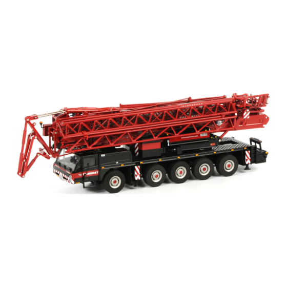
The AT5 truck is built to serve as carriage for the Spierings folding crane, model SK598. For operation, technical
data and maintenance of this folding crane we refer to the subjoined manual.
Because the AT5 is provided with five axles, of which 3 axles are steered, excellent mobility is guaranteed on the
work site as well as on the road. The axles are hydro-pneumatically suspended, whereas the height can be
adjusted and/or blocked. Three axles are driven by a 12.6 litres DAF diesel engine and a gearbox with sixteen
gears forward and two gears reverse. After the gearbox is a high/low gear shift (transfer case), which has two
different gears and a neutral. A gear for driving on the road and a gear for driving off the road. Neutral serves for
the generator drive by the high/low gear shift PTO.
Furthermore, there is a hydraulic system for operating the crane's outrigger system and, when the crane is not
equipped with a separate engine on the upper frame, the truck has a 400 Volt generator to provide the crane with
the necessary power.
The following items are dealt with in this manual.
General data. In this chapter you will find a description of the measurements and technical specifications.
Location and explanation of controls.
Operating the AT5. This chapter gives you instructions for optimal use of the truck.
Maintenance of the AT5, maintenance schedules as well as explanation of the maintenance work to be
carried out. You will also find a maintenance plan containing the specification of the used parts and
lubricants.
Specification of drive line and steering system parts
Explanation of the hydraulic, pneumatic and electrical system.
You will find the outline drawings and diagrams referred to at the back of this manual in the enclosures.
Due to the continuous product development at Spierings Kranen the descriptions and pictures may not be all together similar to the condition on your vehicle.
Copyright 2003. No part of this publication may be reproduced or published, in any form or in any way, by print, photo print, microfilm or any other means without prior
permission from the manufacturer.
AT5-UK-030626
01-12-09
MANUAL SPIERINGS TRUCK AT5
I
Advertisement
Table of Contents

Related Manuals for SPIERINGS AT5


Summary of Contents for SPIERINGS AT5
- Page 1 You will find the outline drawings and diagrams referred to at the back of this manual in the enclosures. Due to the continuous product development at Spierings Kranen the descriptions and pictures may not be all together similar to the condition on your vehicle.
-
Page 2: Table Of Contents
3.2.4. Welding ......................3-1 3.2.5. Environment ..................... 3-2 3.2.6. Cleaning of components .................. 3-2 3.3. Maintenance plan truck AT5 ..................3-3 Periodic checks ........................4-1 4.1. Daily checks ........................4-1 4.1.1. Check engine oil level ..................4-1 4.1.2. Check coolant level ..................4-1 4.1.3. - Page 3 MANUAL SPIERINGS TRUCK AT5 4.2. Weekly checks ....................... 4-2 4.2.1. Check for leaks (oil, air, coolant) ..............4-2 4.2.2. Windscreen washer fluid level ................. 4-2 4.2.3. Clutch fluid level ....................4-2 4.2.4. Draining air vessels ..................4-3 4.2.5. Draining and bleeding fuel system water separator ......... 4-3 Lubrication ..........................
- Page 4 MANUAL SPIERINGS TRUCK AT5 6.8.3. Change oil in transfer case ................6-12 6.9. Axles/brakes ........................ 6-13 6.9.1. Specification axles/brakes ................6-13 6.10. Carrying out maintenance work axles/brakes .............. 6-13 6.10.1. Checking oil level differential housings and hubs .......... 6-13 6.10.2. Change oil ...................... 6-13 6.10.3.
-
Page 5: General Data At5
The chassis is an especially rigid structure to create a good crane support. In Picture 1-1 you will find the measurements of the SK598 with the AT5 carriage. The dimensions given are the overall dimensions, axle bases and turning circle. - Page 6 MANUAL SPIERINGS TRUCK AT5 Axle four and five can be uncoupled mechanically. Independent rear axle steering is now possible using a small joystick. Lift axle three to use this option. Hydraulic powered steering system. Fitted with an emergency steering pump, so when the main steering pump or diesel engine malfunctions, the truck remains steerable until it is at a standstill.
- Page 7 MANUAL SPIERINGS TRUCK AT5 Identification: Engine number: left-hand side on the engine block above the fuel pump. Carriage frame number: on the identification plate in the co-driver's leg-room (See Picture 1-2) and stamped in the right frame girder in front of the first axle (See Picture 1-3).
-
Page 9: Operation
MANUAL SPIERINGS TRUCK AT5 2. Operation 2.1. Get to know the truck Picture 2-1 AT5-UK-030626 01-12-09... - Page 10 MANUAL SPIERINGS TRUCK AT5 1a. Truck cab Besides driving the crane, with the controls in the truck cab you can support the crane on outriggers, adjust the carriage axle height and switch the generator on and off. 2a. Hydraulic oil tank / battery box On this side of the truck, under the engine cowling, you will find the hydraulic oil tank (See Picture 2-2, nr.3) and air cleaner (nr.2).
- Page 11 MANUAL SPIERINGS TRUCK AT5 Picture 2-3 Fuel tank The fuel tank capacity is 600 litres. Bumper The crane has a standard bumper at the rear. When the bumper is folded up, the towing hook can be used (refer “Driving with a trailer”).
-
Page 12: Truck Cab
MANUAL SPIERINGS TRUCK AT5 12. Central lubricating system This is the grease reservoir for the truck's central lubricating system. 13. Concrete bucket / brick gripper support (optional) On the bumper a support can be mounted to carry a concrete bucket or a brick gripper. - Page 13 MANUAL SPIERINGS TRUCK AT5 Seats The cab has room for the driver and a co-driver. Only the driver's seat has pneumatic suspension. The seats' position can be adjusted. This should only be done when the vehicle stands still. A) Back adjustment...
- Page 14 MANUAL SPIERINGS TRUCK AT5 Picture 2-7 Battery charger remote control batteries You will find the battery charger for the remote controls on the left under the dashboard at the driver's side (See Picture 2-7). Every remote control comes with 2 batteries each.
-
Page 15: Control Panel
MANUAL SPIERINGS TRUCK AT5 2.3. Control Panel Picture 2-8 Indicator lamp steering pressure circuit Switch outrigger rear right-hand side Switch PTO Indicator lamp parking brake retract/extend Switch position high/low gear shift, high/low, Indicator lamp steering pressure circuit 2 Switch outrigger beam rear right-hand side... - Page 16 4a. Indicator lamp retarder This lamp lights when the retarder is switched on. 4b. Indicator lamp fluid torque converter running Refer to “Driving the Spierings Crane” 5a. E-gas diagnosis lamp/switch This lamp starts flashing, when a error occurs. To reset the system: Turn off the engine and ignition Push this button and turn on the ignition.
- Page 17 MANUAL SPIERINGS TRUCK AT5 Light switch By pressing this switch halfway, the parking lights are switched on. By pressing the switch all the way, the dipped beams are switched on. Dimmer dashboard lighting When switching on the vehicle lighting also the dashboard lighting goes on. With this dimmer you can change the dashboard lighting intensity.
- Page 18 MANUAL SPIERINGS TRUCK AT5 15. Switch axle 3 left-hand side up/down LEFT 3-4(-5) With this switch the cylinders on the left side of the third, fourth and fifth axle can be moved in and out. 16. Switch axle 3 right-hand side up/down...
- Page 19 MANUAL SPIERINGS TRUCK AT5 23. Switch outrigger front left-hand side retract/extend 24. Switch outrigger beam rear left-hand side retract/extend 25. Switch outrigger rear left-hand side retract/extend 26. Switch outrigger front right-hand side retract/extend 27. Switch outrigger beam front right-hand side retract/extend 28.
- Page 20 MANUAL SPIERINGS TRUCK AT5 By moving the lever to set you can decrease the speed. Keep the lever down until you reach the desired speed. Memo: When you brake or press the clutch, the speed control will switch off. By moving the lever to “memo”, the speed control will switch on again.
- Page 21 MANUAL SPIERINGS TRUCK AT5 Note: registration of crane operation by the tachograph is not laid down by law. Picture 2-9 39. Revolution counter On this counter you can read the diesel engine rpm. The revolution counter has a built-in hour counter.
- Page 22 MANUAL SPIERINGS TRUCK AT5 48. Switch/indicator lamp transverse differential lock 51. Switch/indicator longitudinal differential lock Heating With this selector switch the heating fan can be set at 3 speeds and switched off. By turning this rotary knob the heat supply can be continuously regulated.
- Page 23 MANUAL SPIERINGS TRUCK AT5 67. Vacuum brake/engine stop 68. Steering column switch (See Picture 2-10) Picture 2-10 With this switch the direction indicator is controlled. Pushing the switch forward switches on the full beam headlight. Pulling the switch backwards you can give light signals (F).
-
Page 24: Driving The Spierings Crane
MANUAL SPIERINGS TRUCK AT5 84. Aeronautical warning light on tower head and jib head (optional) With this switch the aeronautical warning light on the tower head and jib head can be switched on and off. 2.4. Driving the Spierings crane The driver is expected to have a driving license for driving a heavy truck and have sufficient technical knowledge. -
Page 25: Driving Off
MANUAL SPIERINGS TRUCK AT5 2.4.2. Driving off In order to drive off, the air-pressure in the system must be at least 5.5 bar. Below this pressure the clutch can not be pressed and the parking brake can not be released when operated. -
Page 26: Stopping
MANUAL SPIERINGS TRUCK AT5 Caution! While gearing down from high to low range, the driving speed must be below Reverse gear is not synchronized, it may only be engaged when the vehicle stands still and the engine runs at idling speed. Also in reverse you can use the high and low splitter. -
Page 27: Longitudinal Differential Lock
MANUAL SPIERINGS TRUCK AT5 2.5.2. Longitudinal differential lock When there is insufficient traction while driving off the road, the longitudinal differentials can be locked with button "longitudinal differential lock". Engagement of the longitudinal differential lock is indicated by the indicator lamp next to the button. -
Page 28: Braking System
MANUAL SPIERINGS TRUCK AT5 2.6. Braking system All axles are equipped with drum brakes. The crane is equipped with three braking systems: Operating brake Parking brake (of axle 2, 3 and 4) Vacuum brake/engine stop The crane can also be provided with an optional retarder. -
Page 29: Parking
MANUAL SPIERINGS TRUCK AT5 In case of frequent use of the retarder the oil temperature can rise considerably. If so, the retarder control reduces the braking force. Keep an eye on the oil temperature gauge while the retarder is in use (See Picture 2-12). As soon as the indicator enters the red (130-150°C) the oil temperature has risen too high. -
Page 30: Towing The Crane
Couple the towing vehicle with a coupling-rod to the front of the crane and tow it slowly away from the dangerous situation. Then contact the service department. In case of doubt always contact the Technical Department of Spierings Kranen. always contact spierings kranen before towing the crane over a bigger distance with higher speed(>20 km/u) -
Page 31: Independent Rear Axle Steering
MANUAL SPIERINGS TRUCK AT5 2.10. Independent rear axle steering With this option, it is possible to steer axle 4 and 5 hydraulic, independent from the other steered axles. By doing so, sideway driving is possible. To drive with independent rear axle steering the crane should be folded entirely. -
Page 32: Driving With Erected Tower
MANUAL SPIERINGS TRUCK AT5 To switch back to normal driving situation, you have o proceed as follows: Retract the cylinders until axle 3 (almost) reaches the ground. Steer the rear axle until the steering arm are in line (orange lamp will go on). -
Page 33: Axle Height Adjustment
MANUAL SPIERINGS TRUCK AT5 2.12. Axle height adjustment The carriage axles are connected to the chassis by means of hydraulic cylinders. Each cylinder is provided with an accumulator, so that the axles can compress. The suspension system can be controlled from the truck cab (See Picture 2-16). - Page 34 MANUAL SPIERINGS TRUCK AT5 “Blocking” (T) In this mode the axles can not compress, enabling a stable travel. In blocking mode the indicator lamp on the switch for blocking/driving is on. In this mode the axles can be moved up or down separately by means of 4 switches.
-
Page 35: Maintenance
MANUAL SPIERINGS TRUCK AT5 3. Maintenance 3.1. General In this part of the manual the crane maintenance is dealt with. After some safety rules, you will find the maintenance plan and the daily and weekly checks for the crane driver/operator. -
Page 36: Environment
MANUAL SPIERINGS TRUCK AT5 3.2.5. Environment In order to reduce environmental pollution to a minimum we advise you to comply with the following rules: Do not pour used oils, hydraulic fluid or coolant in sewers or in the ground. Make sure all used fluids are separated and sent to the respective authorities for destruction or recycling. -
Page 37: Maintenance Plan Truck At5
MANUAL SPIERINGS TRUCK AT5 3.3. Maintenance plan truck AT5 The following maintenance plan is drawn up in order to optimally combine the maintenance work of various AT5 components. In consultation with Spierings Kranen a different maintenance plan can be drawn up. You can also work with maintenance plans for the separate components. - Page 38 MANUAL SPIERINGS TRUCK AT5 Check the oil level in differential Axles cases and hubs, top up if necessary Suspension / steering system See “Lubrication” Check the connections Hydraulic system See “Lubrication” Carry out a visual check of oil...
-
Page 39: Periodic Checks
MANUAL SPIERINGS TRUCK AT5 4. Periodic checks 4.1. Daily checks 4.1.1. Check engine oil level To check the oil level you will find a dipstick (1) at the truck cab rear left-hand side. There is also a filler hole (with red cap) for topping up engine oil (2). -
Page 40: Tyres And Rims
MANUAL SPIERINGS TRUCK AT5 Put the heater knob on “warm”. Remove the (blue) cooling system filler cap. Leave the engine running for some seconds. Switch off the engine and check the fluid level and top up, if necessary, until the level is halfway the filler neck. -
Page 41: Draining Air Vessels
MANUAL SPIERINGS TRUCK AT5 4.2.4. Draining air vessels The (60 litres) air vessels for circuit 1 and 2 are directly behind axle 3. The air vessels for the parking brake (60 litres) and for accessories (10 litres) are at the right-hand side between axle 2 and 3. The 5-litres tank is at the right-hand side before axle 1. -
Page 43: Lubrication
MANUAL SPIERINGS TRUCK AT5 5. Lubrication To grease the grease points the carriage is fitted with a central lubricating system. A number of grease points have to be greased manually. (See “Manual lubrication”) 5.1. Central lubricating system This system is controlled by a switch clock on which the grease time in relation to the operating time can be set (See Picture 5-1). - Page 44 MANUAL SPIERINGS TRUCK AT5 The points covered by the central lubricating system are: Steering knuckle (at the top and Steering arm hinge points bottom) Suspension axle Fusees boven en onder Intermediate bearing steering shaft Gear shift lever ball The points not covered by the central lubricating system (thus having to be greased manually) are: (for location refer to “Manual Lubrication”)
-
Page 45: Manual Lubrication
MANUAL SPIERINGS TRUCK AT5 5.2. Manual lubrication 5.2.1. Outrigger-cylinders In Picture 5-3 you see the grease nipple on the outrigger-cylinder (nr.1). Push out the outrigger-beams until the holes in the beams are outside the chassis. Through these holes, you can reach the grease nipples (1 per outrigger beam). -
Page 46: Cardan Shafts
MANUAL SPIERINGS TRUCK AT5 5.2.4. Cardan shafts The cardan shafts make up the connection between gearbox, transfer case, generator and axles. The cross pieces must be greased regularly through the grease nipples (See Picture 5-6). This does not apply to the drive shaft between the transfer case and the generator (G). -
Page 47: Steering System
MANUAL SPIERINGS TRUCK AT5 5.2.5. Steering system The various steering rods ball couplings are maintenance-free. Only the steering rod spline bushings must be lubricated (see Picture 5-8, nr. 13). The lubrication interval is every two months (or 350 hours). The grease to be used is EP2 grease. -
Page 49: The Drive System
MANUAL SPIERINGS TRUCK AT5 6. The drive system The picture below shows the drive system make-up. The separate components are described on the following pages. Successively: Diesel engine (A) Clutch and gearbox with fluid torque converter an retarder (B) ... -
Page 50: The Diesel Engine
MANUAL SPIERINGS TRUCK AT5 6.1. The diesel engine 6.1.1. Specification diesel engine As drive source the Spierings AT5 is fitted with a DAF-turbo diesel engine with intercooler. Data: Brand/type: DAF XF 315 M Fuel system: Water cooled four stroke with direct injection... -
Page 51: Maintenance Activities X Service Interval
MANUAL SPIERINGS TRUCK AT5 6.2.2. Maintenance activities X service interval Change the engine oil Change the oil filter Cleaning, air-filter element Replace the fuel filter Check all the components and hose connections for leaks ... -
Page 52: Air Cleaner Cleaning/Replacement
MANUAL SPIERINGS TRUCK AT5 6.3.3. Air cleaner cleaning/replacement The air cleaner element may be cleaned with compressed air only once, and then it must be replaced. Before cleaning or replacing the air cleaner element, the air cleaner housing (behind the left-hand engine cowling) must be removed. -
Page 53: Change Filter Element Water Separator
MANUAL SPIERINGS TRUCK AT5 6.3.5. Change filter element water separator Regularly check the water separator and drain water and dirt if necessary. 1. Put a trough under the water separator. 2. Unscrew the drain plug (3) some turns and drain the water separator. -
Page 54: Inspections
MANUAL SPIERINGS TRUCK AT5 6.4. Inspections 6.4.1. Check for fuel leaks Visually check the fuel system for leaks, pay special attention to the synthetic fuel lines attached to components or in line bundles. In case the synthetic fuel line's condition is such that rubbing through is expected or already visible, it must be replaced. -
Page 55: Check Coolant Antifreeze Concentration
6.5.1. Specification gearbox The ZF 16S-221 gearbox, installed in the AT5, has sixteen gears forward and two gears reverse. The gearbox has an integrated fluid torque converter and a retarder. The gearbox shifts automatically (by means of air pressure) between the low and high range. -
Page 56: Bridging Clutch
MANUAL SPIERINGS TRUCK AT5 Picture 6-8 The ratio between the torque of the turbine wheel and the pump wheel is called the torque enlargement. The ratio is bigger when the numbers of revs are more different. So the torque is maximal, when the turbine wheel is standing still. At the moment the number of revs of the turbine wheel is 80% of the number of revs of the pump wheel, there isn’t any torque enlargement. -
Page 57: Retarder
MANUAL SPIERINGS TRUCK AT5 6.5.5. Retarder The retarder is placed between the torque converter and the clutch. The retarder consists of: A stator, connected to the gearbox housing. A rotor, connected to the ingoing shaft of the gearbox. -
Page 58: Drain Oil Gearbox
MANUAL SPIERINGS TRUCK AT5 6.6.2. Drain oil gearbox The oil must be drained while it is still warm. To drain, remove drain plugs of the converter (5) and the gearbox (6). It is not possible to drain all of the oil. But by removing plug A (See Picture 6-10 (bottom view)) you can remove some more oil (approx. -
Page 59: Take Off And Replace The Suction Filter
MANUAL SPIERINGS TRUCK AT5 6.6.5. Take off and replace the suction filter Remove the cover (B in Picture 6-10 (bottom view)) Unscrew the bolt of the filter and remove the filter Clean or change the filter (See “Technical data”) ... -
Page 60: The Transfer Case
MANUAL SPIERINGS TRUCK AT5 6.7. The transfer case 6.7.1. Specification transfer case The transfer case is a STEYR type VG2001/396. This transfer case divides the power at the inlet (No.1, by means of a cardan shaft connected to the driven shaft of the gearbox) over two outlets. -
Page 61: Axles/Brakes
Specification axles/brakes The truck AT5 has five axles. All five axles are Ginaf axles. Axle 1, 2, 4 and 5 are steered. Axles 2, 3 and 5 are driven through the transfer case. The crane weight is divided evenly over the axles; the axle load is 12,000 kg per axle. -
Page 62: Check The Brake Lining Thickness
MANUAL SPIERINGS TRUCK AT5 The hubs have one filler/drain (plug A) and an oil level check (plug B). Drain the old oil by turning the drain hole downwards and removing the filler/drain plug. Now turn the hole upwards and fill the hub up to the hole with approx.1.1 litre oil. -
Page 63: The Hydraulic System
MANUAL SPIERINGS TRUCK AT5 7. The hydraulic system 7.1. Structure hydraulic system The hydraulic diagram shows how the hydraulic system is built up (see enclosure). The hydraulic system exists of 4 subsystems, i.e.: Hydraulic pump system Hydraulic steering system ... -
Page 64: Hydraulic Steering System
MANUAL SPIERINGS TRUCK AT5 7.1.2. Hydraulic steering system Picture 7-1 shows how the steering system is built-up. In the steering gear housing (A) the turning motion of the steering wheel is mechanically converted to the motion of the steering rods (B). These in turn operate the steering... -
Page 65: Hydraulic Suspension
Picture 7-2 7.2. Maintenance Hydraulic System All parts of the hydraulic system are built for a long service life without to much maintenance. Spierings advises you to adhere to the following maintenance plan: Replacing the fine filter and return oil filter: ... -
Page 66: Check Oil Level
MANUAL SPIERINGS TRUCK AT5 7.2.1. Check oil level To check the oil level a gauge glass (1) is mounted on the hydraulic oil tank. All cylinders (including the suspension cylinders) must be retracted when checking the oil level. The oil level must be in the upper part of the gauge glass (approx. -
Page 67: The Steering System
(circuit 2) show which circuit is defective. 8.1. Maintenance Steering System 8.1.1. Align To prevent excessive tyre wear we advise you to align the truck every year. Please contact Spierings cranes for instructions. 8.1.2. Check steering arms and ball joints for play Check this with help of another person. -
Page 69: The Pneumatic System
MANUAL SPIERINGS TRUCK AT5 9. The Pneumatic System 9.1. Structure Pneumatic System The pneumatic diagram in the enclosure shows how the pneumatic system is built up. The pressure is supplied by a compressor on the DAF engine. The system can be divided into 2 subsystems: The system for the truck brakes (approx. -
Page 70: Maintenance Pneumatic System
MANUAL SPIERINGS TRUCK AT5 Axles: - switching transverse differential locks axles 2, 3 and 4. - switching first axle drive (option) Steering system - Cylinder (un-)locking the steering arm of axle 4. 9.2. Maintenance Pneumatic System 9.2.1. Change filter element air-dryer Important for proper operation and long service life of the pneumatic system is a dry and clean compressed air condition. -
Page 71: Electrical System
MANUAL SPIERINGS TRUCK AT5 Electrical System 10.1. Structure Electrical System The on-board voltage is 24 Volt. It is supplied by two 12 Volt 165 Ah batteries, series connected. They are charged by a 24 Volt AC dynamo, with a maximum charging current of 35 A. The batteries are situated under the right-hand engine cowling (refer “get to know the truck”). -
Page 72: Lighting
MANUAL SPIERINGS TRUCK AT5 10.1.3. Lighting Table 10-1 is a survey of all lamps. Of each lamp the number, the capacity and the id number is mentioned. Table 10-1 Survey Lamps Name Number Capacity ID Number Head light 75/70 W... -
Page 73: Maintenance Electrical System
MANUAL SPIERINGS TRUCK AT5 10.2. Maintenance Electrical System The batteries maintenance exists of regularly checking the fluid level. If necessary it must be topped up with distilled water. 10.2.1. Charging batteries You need a charger to charge the batteries and a cable with (2-pole) NATO-connector (charger and cable not provided). -
Page 75: Technical Data
Oil gearbox 2104 (at delivery) ELF: PERFORMANCE XR30 SAE 20W-20 AP/CF/ACEA E1-96 MIL-L- Oil gearbox 2104 (after 400 h inspection at Spierings’) ELF: PERFORMANCE XR30 Brake fluid DOT 4 Clutch fluid ELF: Frelub 650 Filter element gearbox AAVE00150020 Gasket for gearbox-filter... - Page 76 MANUAL SPIERINGS TRUCK AT5 Hydraulics ATF Dexron-IID, -IIE, -III or Mercon-M Oil hydraulics (±100 litres) ELF: Elfmatic G3 22051 Return oil filter hydraulic system CS-15AN (OIIIT) HYIN04100211 Miscellaneous Grease (general) Grease autom. lubricating system AVIA: Mystiek JT-6 Oil air lubricator ISO/UNI FD22 (e.g.
-
Page 77: Enclosures
MANUAL SPIERINGS TRUCK AT5 Enclosures Enclosure 1 Hydraulics Enclosure 2 Pneumatics Enclosure 3 Electrical diagram’s Enclosure 4 Electrical connections 12-1 AT5-UK-030626 01-12-09...
Need help?
Do you have a question about the AT5 and is the answer not in the manual?
Questions and answers