
Summary of Contents for Miovision SmartView 360
-
Page 1: Table Of Contents
Package contents 2 Required tools (not included) 3 Installation requirements 3 Safety recommendations 4 Planning your SmartView 360 installation 4 Determining the number of cameras to install 4 Single-camera installations Dual-camera installations 6 Deployment Guidelines 8 SmartView 360 installation 9 ... -
Page 2: Package Contents
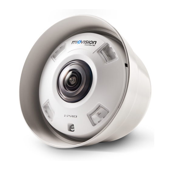
Package contents SmartView 360 components SmartView 360 Assembly Camera with mount. For mast arm installation, the appearance of the mount differs. Additional included components: ● Silicone weatherproof tape ● Torx security bit ... -
Page 3: Required Tools (Not Included)
Required tools (not included) ● Bucket Truck: Schedule a bucket truck with a minimum reaching height of 9.14 m (30 ft). ● Stainless steel banding - 12.7 or 19 mm (½ in or ¾ in) band width recommended ● Banding tool ●... -
Page 4: Safety Recommendations
● If possible, inspect wires in the cabinet and traffic pole for any unsafe wear and replace them if necessary. Planning your SmartView 360 installation Determining the number of cameras to install TrafficLink Detection supports single and dual-camera installations with the SmartView ... - Page 5 In those scenarios, install a second camera to optimize detection and limit the potential for objects to obstruct vehicles, or vehicles to obstruct one another. 6.11.19 5 ...
-
Page 6: Dual-Camera Installations
Dual-camera installations Larger intersections require a second camera. See the t able below for guidelines. Dual-camera installations can also improve pedestrian data accuracy in C ontinuous TMCs . See the M ultimodal Detection - Dual Camera Setup video for more information. ... - Page 7 Camera height Maximum distance from camera To front of zone To back of zone 8.5 m (28 ft)* 42.67 m (140 ft) 54.86 m (180 ft) 9.1 m (30 ft) 45.72 m (150 ft) 57.91 m (190 ft) 9.75 m (32 ft) 48.77 m (160 ft) 60.96 m (200 ft)
-
Page 8: Deployment Guidelines
Deployment Guidelines 1. Determine which traffic pole you will use to mount the SmartView 360. This is typically the traffic pole nearest your traffic cabinet, but could be a different traffic pole to meet these requirements: ○ It must be the traffic pole nearest the intersection. ... -
Page 9: Smartview 360 Installation
SmartView 360 installation Camera mounting options Miovision offers the following camera mounting options: Camera Bell Assembly The camera bell assembly does not include a mount and is intended to be installed on a customer-supplied mount. ● Dimensions: 196.85 x 196.85 x 152.4 mm (7 ¾ x 7 ¾ x 6 in) ... -
Page 10: Bell Assembly Installation Steps
Bell Assembly Installation Steps Components ● SmartView 360 Bell Assembly - 38.1 mm (1.5 in) NPT thread ● Rubber camera gasket ● Thread seal tape Required materials (not included) ● Customer-supplied mount 1. Install the rubber camera gasket onto the mount. Fold the gasket back to allow ... -
Page 11: Vertical Mount
3. Position the rubber camera gasket to cover the gap between the camera mount and the bell. Vertical Mount The vertical mount is intended to be mounted directly on a hollow traffic pole or pole extension. -
Page 12: Horizontal Mount
● Dimensions: 482.6 x 368.3 x 203.2 mm (19 x 14.5 x 8 in) ● Weight: 3.4 kg (7.5 lbs) ● Mount Material: Aluminum Horizontal Mount The horizontal mount is intended to be installed on a mast arm. It is secured to the horizontal traffic arm through the mount bracket using two lengths of 19.05 mm (3/4 in) ... -
Page 13: Installation Steps
SmartLink. If your application requires a TrafficLink Interface, you will also install the Interface before installing the SmartView 360. Connect the Ethernet cable to the camera Loosen the camera set screw using the provided Torx security bit. ... - Page 14 To release the camera from the mounting plate, apply downward pressure on the camera housing and then rotate the camera housing counter-clockwise. Before you install/crimp the RJ45 connector, position the coupler on one end of the Ethernet cable. 6.11.19 ...
- Page 15 Install/crimp the RJ45 connector using pinout TIA568-B. Make sure that the Ethernet cable drain wire is connected to the metal shield on the RJ45 connector. Test the cable run connections/shield. 6.11.19 15 ...
- Page 16 Connect the RJ45 connector into the coupler on the camera module, connect the coupler, and then rotate the coupler clockwise to lock. When the coupler is properly locked, the arrows on coupler line up. Make sure that the coupler is kept dry during installation. ...
- Page 17 6.11.19 17 ...
-
Page 18: Mount The Smartview 360
The tab on the side of the camera should move from Open to Lock. Using the Torx bit, tighten the set screw until it is snug. Mount the SmartView 360 If you prefer to review these steps in a video tutorial, see S martView 360 installation . ... - Page 19 1. If you are installing the SmartView 360 on a mast arm, the camera arm is rotated 180 degrees for shipping. To rotate it to the correct angle for installation, loosen the nuts shown in the following diagram, rotate the camera arm, and then tighten ...
- Page 20 2. Put the clamp in an appropriate location on the mast arm 3. Replace the nuts and tighten the clamp. 5. Rotate the SmartView 360 so that it points toward the center of the intersection, free of visual obstructions. 6.11.19 20 ...
-
Page 21: Connect Smartview 360 To Smartlink
6. After the SmartView 360 is in position, tighten the socket nuts with a 7.9 mm (5/16 in) socket wrench. 7. Run the Shielded Ethernet Cable through the hole in the traffic pole, leaving leaving 0.9 to 1.2 m (3 to 4 ft) of slack to follow proper drip loop procedure. N ote: ... -
Page 22: Test Your Installation
S martLink on-site troubleshooting for more information. Technical support Technical support is available five days a week by phone or email during regular business hours (Monday-Friday, 7 am - 6 pm EST/EDT.) Certain restrictions and exclusions apply. Online:help.miovision.com Phone:1-855-360-7752 Email: support@miovision.com 6.11.19 22 ...
Need help?
Do you have a question about the SmartView 360 and is the answer not in the manual?
Questions and answers