Table of Contents
Advertisement
Quick Links
Advertisement
Table of Contents

Summary of Contents for xxter xxter
- Page 1 Installation manual...
- Page 2 Version 2.5 – Maart 2020 © 2020 xxter bv. All rights reserved. Screenshots in this manual and the actual screens on your computer can be different. Updates are made to the website and the products on a regular basis. More information can be found at www.xxter.com xxter installation manual...
-
Page 3: Table Of Contents
Contents 1. Introduction 2. xxter configuration overview 3. Project configuration 7 4. xxter basic installation 5. Registration 6. Configuring KNX components 7. Configuring Artnet components 8. Connecting the device 9. Set-up 10. Teaching-in enOcean components 11. Setting up Hue components 12. Initialization 13. Using xxter over the Internet 14. Updating firmware 15. Reset options and status LEDs 16. Programming KNX through xxter 17. Service and support Addendum A (component types) xxter installation manual... - Page 4 Welcome With xxter you can expand the possibilities of an automated home or office in only a few steps and control it with a smartphone, tablet or pc. This manual is intended for the installation professional and starts with a short explanation of the workings and configuration options of xxter. In the following chapters you will be taken through the steps for initial registration, configuration, connecting the device and initialisation. The explanation of how the visualisation for smartphones, tablets and pc’s can be created and adapted is included in the user manual. This makes it possible for the end-user to fine tune xxter completely to his or her personal needs. The installation manual expects you, the installation professional, to have basic knowledge on Ethernet networks and the applied home automation standards (KNX/ETS, enOcean, Artnet DMX, Hue). We often refer to the end-user. The end-user is the intended person to use xxter after installation. More information on the use of xxter can be found in the user manual. This manual only describes the basic installation of xxter. For additional options and extensions like cameras, intercom systems, audio controls (e.g. uPnP and Sonos), graphs, scripts and many other options, separate manuals are available. Please refer to www.xxter.com for more information. xxter installation manual...
-
Page 5: Introduction
1. Introduction With xxter you can easily control an automated home or office with a smartphone, tablet or Windows computer, at home or over the Internet when you are away. Additionally, xxter gives you the possibility to connect the different home automation standards to each other and integrate it in one environment. Image 1: xxter overview The configuration of xxter is performed on xxter’s central servers. This configuration is then downloaded on the xxter device itself and in the app. In the following chapters, this central configuration is explained in more detail. xxter installation manual... -
Page 6: Xxter Configuration Overview
2. xxter configuration overview The xxter configuration is created in four separate parts: devices, projects, profiles and pages. The device is the xxter unit itself. The device should be registered by the installation professional as well as the end-user and is the basis for the rest of the configuration. The project contains the actual technical configuration, wherein the home automation components are defined as well as additional other features, like for instance cameras. By connecting a project to a device, this configuration will be enabled for that device. The profile describes the visualisation for smartphone, tablet and pc. By connecting a profile to a device, the visualisation will become available for that device. The pages are the different visualisation screens to control a profile. Every profile has one page as index page and any number of following pages. As an installation professional you can configure the project and connect it to a device. Of course it is possible to manage multiple projects and devices for one professional. As an end-user you can manage the profile and the subsequent pages. It is possible to use multiple devices and profiles next to each other. On the smartphone, tablet or pc you can choose which profile you want to load for the specific device. This manual describes the configuration of the device and the project. For more information about managing profiles and pages, please refer to the user manual. The installation professional also has access to the section for the end- user in the configuration environment. xxter installation manual... -
Page 7: Project Configuration
3. Project configuration Every project is built from components and every component has a type, a name and group addresses to identify the component. The type of the component has to correspond with the characteristics of the home-automation component that is used. For an overview and explanation of the different component types, see addendum A. The name of a component is important for identification by the end- user, so he or she understands which component was intended, for instance ‘Kitchen table ceiling light’. The end-user can always use another description when including the component in the visualisation. For the technical identification of the component, group addresses are used: The sending group contains the group address to which a telegram should be sent. There is a maximum of one sending group address per component The status group(s) contains one or more group addresses to display the status of that component. Often the sending group address is also a status group. The value contains the value that should be sent or the value on which xxter should react. The group addresses are used for all different protocols of home- automation: KNX, DMX, enOcean and Hue. Details about these protocols can be found in the corresponding chapters, later on in this manual. Apart from these main settings, you can set-up whether xxter should perform a bridge function for a component, between the different protocols, for instance between KNX and enOcean. For every component you can also select whether the component should be available for the end-user to use as a scenario option or in the planner. Normally all actuators that are used by regular switches in the house should also be available for scenarios and the scheduler (e.g. lights, curtains, etc). xxter installation manual... - Page 8 Projects can be configured through the central webpages of My xxter. For teaching-in enOcean telegrams, the configuration tool is required. You can find the tool on the downloads page for professionals within My xxter: http://www.xxter.com/myxxter. Image 2: project configuration example on My xxter Scenarios With the use of scenarios, the end-user can easily select a set of actions to perform with a single push on a button. The end-user can manage the scenarios himself, but to be able to use the scenarios from the automated home, it is important that the installation professional initially creates a set of scenarios, to which xxter will react. xxter will listen to the specified group address and value. When a KNX or enOcean switch sends a telegram to one of these addresses, xxter will perform that scenario. Scenarios for which the installation professional has entered a group address can never be deleted by the end-user. Scenarios can also be used from within the visualisation. The end-user can always change the name of a scenario. How to configure and use scenarios is explained in the user manual. xxter installation manual...
-
Page 9: Xxter Basic Installation
4. xxter basic installation Now the basic concepts of xxter are explained, we can start with the installation. The basic installation of xxter consists of the following steps: 1. Registration [chapter 5] 2. Configuring home automation components a. KNX [chapter 6] b. Artnet DMX (RGB led) [chapter 7] 3. Connecting the device [chapter 8] 4. Set-up [chapter 9] 5. Teaching-in home automation components a. enOcean [chapter10] b. Philips Hue [chapter 11] 6. Initialisation [chapter 12] The configuration of KNX and DMX components can be prepared beforehand (for example from the office), before the xxter unit is physically connected and set-up. To teach in enOcean and Hue components, the specific home automation components as well as the xxter unit have to be installed. In case you want to prepare this from the office, a test setup has to be created, similar to the desired setup at the intended user location. After the basic installation has been performed, the visualisation from the smartphone or tablet can be configured. The instructions for the visualisation can be found in the user manual. Apart from the basic installation, xxter also supports cameras, intercom systems, audio controls (e.g. uPnP and Sonos), graphs, scripts and many other features. Separate manuals are available for these features on the website www.xxter.com. -
Page 10: Registration
5. Registration Every xxter product has to be registered before use. After registration the installation professional can configure the xxter and the end-user can personalize it. Therefore, it is required to register xxter by the professional as well as for the end-user. For the registration of xxter, please follow the registration help on: http://www.xxter.com/register Image 3: Registration help Please remember the usernames and passwords well, because they are needed for the rest of the installation. The serial number of the device can be found on the device itself and on the packaging. xxter installation manual... -
Page 11: Configuring Knx Components
6. Configuring KNX components For the configuration of a KNX installation in xxter, the KNX group addresses will have to be transferred to xxter as components in the project. The easiest way to do this, is by exporting the KNX configuration in ETS as a ‘KNXproj’ extraction and then import it in the project in my xxter, http://www.xxter.com/myxxter. Here you can easily transfer the relevant components from the ETS configuration to the xxter configuration. You can program with ETS directly through the xxter device, see chapter 16. Image 4: xxter project configuration example To configure scenarios, you can manually choose one or multiple free group addresses. These need to be 1-byte (0-255) group addresses with a value between 0 and 255. When a certain value is sent to the specified group by for example a KNX switch, xxter will execute the specified scenario. See also the paragraph scenarios in chapter 3. xxter installation manual... -
Page 12: Configuring Artnet Components
7. Configuring Artnet components To configure Artnet DMX equipment, for instance to control RGB led lighting, the Artnet DMX identification of the specific components must be transferred to the project. Every DMX address will usually have to be included as the sending group as well as the status group. Arnet DMX only supports byte values and can be used with switches, dimmers, sending byte values and RGB led lighting. When a switch is used in combination with a DMX address, that address will be set to 100% when an ‘on’ command is given. A DMX address consists of a universe and an address. The universe can be between 0 and 31 and the address between 0 and 511. In the xxter configuration DMX addresses always contain the prefix “DMX:”, followed by the universe, a “/” and then the address. An example of a DMX address is: DMX:0/12 With which we intend address 12 of universe 0. Image 5: DMX configuration example xxter installation manual... -
Page 13: Connecting The Device
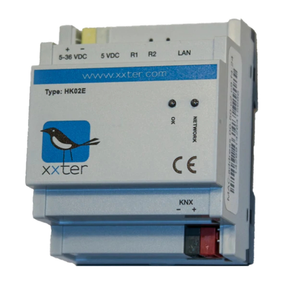
8. Connecting the device The steps to connect the xxter device depend on the model that is used. For all models the UTP cable has to be connected to the (internal) network. xxter must be able to connect to the Internet to be able to download the configuration and for future firmware updates. KNX direct For KNX, connect the bus cable to the KNX connector. Subsequently connect the power adaptor to the 5 VDC adaptor port or other power to the 5-36 VDC white yellow plug. Image 6: xxter device Artnet DMX For the use of DMX components, an ArtNet->DMX node is required. This node must also be connected to the same internal network as the xxter unit. A list of ArtNet->DMX nodes that are tested with xxter can be found on the website. Philips Hue When using Philips Hue, make sure that the xxter unit and the Hue network module (bridge) are both connected to the same internal network. xxter installation manual... - Page 14 In case you are using a xxter model with enOcean support (HKE02), then the enOcean antenna has to be connected to the green enOcean connector. Subsequently connect the power adaptor to the 5 VDC adaptor port or other power to the 5-36 VDC white yellow plug. Image 7: xxter device with enOcean support The enOcean ANE01 antenna is equipped with a repeater function. The ANE01 repeater has three different settings: 1) No repetition (standard): both dip-switches to OFF (numbered side) 2) Repeat only original telegrams (level 1): set only dip-switch 1 to ON 3) Repeat both original and one time repeated telegrams: set both dip-switches to ON To activate a new repeater setting it is required to shortly disconnect the ANE01 from the xxter device. xxter installation manual...
-
Page 15: Set-Up
9. Set-up The following settings need to take place on the xxter unit itself. Access the device on the local network with your web browser using the IP address the xxter device has received. When the device has started successfully and was able to connect to the Internet, you can find the IP address under the link to local settings on My xxter at the devices page. Normally xxter will automatically receive an IP-address through DHCP. You can look up the IP-address that was given out on the DHCP–server or router, after the xxter device has fully started. You can also use the IP-finder tool to find the xxter device. You can find the tool on the downloads page for professionals within My xxter: http://www.xxter.com/myxxter. In case xxter could not reach a DHCP server, it will use the following default settings: IP-address: 192.168.0.150 Net mask: 255.255.255.0 To connect to xxter, your computer has to use a similar IP-address, for instance 192.168.0.10. To continue the set-up, follow the xxter configuration help: Image 8: configuration help xxter installation manual... - Page 16 After the basic settings are completed, the protocol specific settings need to be set. On the xxter unit, open the Settings – Protocols page. KNX direct Under the KNX settings the KNX protocol should be enabled, with the connection method set to ‘Direct’. Verify whether the KNX physical address is not used on the KNX bus by another component. We advise you to reserve this address in KNX as a dummy component, to prevent the address to be used by another device in the future. KNX connection over IP Under the KNX settings the KNX protocol should be enabled. In case you are using the KNXnet tunnel protocol, enter the IP address of the KNX/IP module. In case you are using the KNXnet routing protocol, set this feature to “on” and verify the standard Multicast IP address. enOcean Under the enOcean settings the enOcean protocol should be enabled. Artnet DMX Under the ArtNet settings enter the IP address of the ArtNet receiver. To guarantee the connection between Artnet DMX and xxter after (network) interruptions, xxter can repeat the status of the DMX components in a specified interval. Turn on this feature if desired. Philips Hue Under the Hue settings enter the IP-address of the Hue bridge(s). Then, push the button on the Hue bridge itself and subsequently click the Confirm button. You can connect up to 5 Hue bridges to one xxter. When you open the Status page, you can verify whether the KNX, enOcean and/or Hue are connected correctly. xxter installation manual...
-
Page 17: Teaching-In Enocean Components
Teaching-in enOcean components To teach in enOcean components, the configuration tool is used. You can find the tool on the downloads page on the professional section of My xxter: http://www.xxter.com/myxxter. In the configuration tool, either open a project, download a project from the server or create a new project. Enter the IP address of the xxter device in the tool’s settings and connect to the device using the right-most button in the toolbar (the enOcean symbol). Now the configuration tool can receive enOcean teaching telegrams. The configuration tool will automatically add all received ‘teach-in’ and switch telegrams to the project on the fourth tab of the tool. Image 9: teaching in enOcean telegrams Of course you can also add the sending enOcean telegrams in the configuration tool. For a detailed explanation of the different types of enOcean telegrams and a complete overview of all steps to configure enOcean, please refer to the separate enOcean manual on the website. Here you can also find an overview of all enOcean components that are supported by xxter. xxter installation manual... -
Page 18: Setting Up Hue Components
Setting up Hue components Before using Hue components, make sure that all Hue lights are correctly configured within the Hue system, as described in the Hue manual(s). When xxter has been successfully linked with the Hue bridge (see chapter 9) you can see which Hue lights are available on the status page of the xxter device. On My xxter you can then add the different Hue lights. Always enter a Hue light in the sending group as well as the status group. A Hue light is always defined in the following format: “HUE” followed by the bridge number, “:” followed by the lamp or group number, a “/” and the desired command. For instance, “HUE1:1/S” for switching lamp 1 on bridge 1 on/off. The following commands are supported: Switch Switching on/off RGB lighting Red RGB lighting Green RGB lighting Blue Dimmer HUE Hue (colour) Dimmer SAT Saturation Dimmer BIR Brightness Dimmer Colour temperature To set a certain colour of a Hue light the ‘RGB lighting’ component can be used, or two separate dimmers for setting the Hue and Saturation. The Colour temperature can be used to control the “warmth” of the colour of white light. -
Page 19: Initialization
Initialization Now the installation and configuration is complete, it can be loaded onto the xxter device. Access the device on the local network with your web browser using the IP address of the xxter device and log in. Press the button Load configuration in the top left hand corner of the menu. When the configuration is successfully loaded, the technical installation is completed. Now, using the user manual, the visualisation for the smartphone, tablet or pc can be created and the xxter app installed and set up to connect to the xxter device. We recommend that the installation professional always creates an initial visualisation for, or together with, the end-user. Using xxter over the Internet When the end-user wants to use xxter not only from within the home or office, but also over the Internet, this can be done with either ‘port forwarding’ or with the use of the connect service, a paid service of xxter. More information about the connect service can be found in the user manual in chapter 6. Port forwarding To allow port forwarding, the router, firewall or modem of the end- user needs to be set up to forward the xxter port to the internal IP- address of the xxter device. Please refer to the manual of the router, firewall or modem in question how this should be done. By default the xxter port number is: TCP 2199 It is also possible to configure the xxter device to work on a different port number. This can be done on the Settings – basic page under the ‘advanced network settings’. When using an alternative port number, this should also be explicitly added when configuring the xxter app. For more information on use of xxter over the Internet, please refer to our documentation page on our website www.xxter.com. xxter installation manual... -
Page 20: Updating Firmware
Updating firmware Regularly new versions of the xxter firmware will be released. These releases can add new features, but can also contain bug fixes or improvements. On the xxter website the latest version of the firmware is listed. The xxter device itself can verify whether new firmware is available. Access the device on the local network with your web browser using the IP address of the xxter device and log in. Then open the Settings – system page and in the Firmware section press the Check button to check for firmware updates. In case a new version is available, you will be prompted to update the firmware. By selecting update firmware, the device will download and install the new firmware. This can take some time. After the firmware is successfully updated, the xxter device needs to be restarted. This can be done by clicking Reboot, to reboot the device. Important: never turn off the xxter device while it is updating the firmware! It can be required to update the firmware multiple times in a row, before the xxter device is updated to the latest version. After updating the firmware, we always advise to reload the configuration by pressing the button Load configuration in the top left hand corner of the menu. xxter installation manual... -
Page 21: Reset Options And Status Leds
No Internet connection, only LAN connection* BOTH quick red / green intermittent Currently updating firmware of device *) the Internet connection is only verified during boot and when the Check Internet connection button is pressed on the status page of the xxter device. Image 11: xxter device xxter installation manual... -
Page 22: Programming Knx Through Xxter
Programming KNX through xxter It is possible to program with ETS through the IP address of the xxter device, using the KNXnet/IP tunnel protocol. This access is normally disabled and must be activated by the user explicitly. Access can be granted for a period of 1 hour, 4 hours, 8 hours or indefinitely. After the device is connected and set up, this option can be found on the status page of the xxter device under KNX tunnel input. When the xxter app is installed and set up (see user manual), it is also possible to grant access through the configuration menu on the settings page with the option ‘Allow access to KNX bus’. This way the end-user can grant you as the installation professional temporary access for maintenance. The app will enable access for a default period of 8 hours. In case you want to have access to the xxter device for programming from a remote location (your office), you will need to extend access to xxter over the internet (see chapter 13) with ‘port forwarding’ for UDP on port 3671. With ETS you can then connect to the dynamic DNS address of the xxter device. You can find this address as ‘IP or host (external)’ on the devices page of My xxter. Important: for security reasons, you should not set up external access for programming without a restriction for the time period of the ‘Allow access to KNX bus’ setting. xxter installation manual... -
Page 23: Service And Support
Service and support Answers to frequently asked questions can be found on: http://www.xxter.com/faq On our forum you can exchange information with other professionals: http://www.xxter.com/forum Additional support can be found on: http://www.xxter.com/support In case you are unable to resolve the issue here, you can contact us on support@xxter.com. Please always include the serial number of the xxter device it concerns. Addendum A (component types) In this addendum we supply a short explanation for the project configuration of the most used types of components for home automation. A switch refers to a relay or switch actor and can only be turned on or off. A dimmer refers to a dimming actor and can be set to a scale of 0 to 100%. RGB lighting is a combination of three connected dimmer components for red, green and blue. Together they set one RGB lamp to the desired colour. Bit/Byte values can be used to send or receive values from the home automation installation. The type of component defines what kind of bit or byte value should be used. Sensor values like temperature, wind speed, etc. can be used to read information from the home automation installation, but can also be used to send a value, for instance to set a thermostat temperature. xxter installation manual... - Page 24 Technical specifications Size (lxwxh): 90x72x60mm Type: DIN-module (4 MW) Weight: 100 grams Voltage: 5-36 VDC Power consumption: 1W (avg.) Cooling: passive Accessories: - UTP cable (1 m) - enOcean antenna (only HKE02) - Installation leaflet xxter installation manual...
Need help?
Do you have a question about the xxter and is the answer not in the manual?
Questions and answers