Table of Contents
Advertisement
Quick Links
Advertisement
Table of Contents

Summary of Contents for aguilera electronica AE/SA-C1
- Page 1 ALGORITHMIC PANEL AE/SA-C1 INSTALLATION GUIDE VERSION 1.0 SEP/11...
-
Page 3: Table Of Contents
INSTALLATION GUIDE AE/SA-C1 TABLE OF CONTENTS PAGE INTRODUCTION....................... 5 ......................5 AIM OF THE GUIDE ....................... 5 BSERVATIONS ..................5 WARNINGS AND PRECAUTIONS ........................5 APPROVALS CONTENTS. MATERIAL INCLUDED IN THE PACK..........7 ...................... 7 HECKING THE PANEL ........................ - Page 4 INSTALLATION GUIDE AE/SA-C1 5.2.5 Network diagnostics....................31 AE2NET ’ ..........32 ERIFICATION OF THE NETWORK S OPERATION 5.3.1 Synchronisation..................... 32 5.3.2 At rest........................32 5.3.3 Active........................33 5.3.4 Fault resetting....................... 34 5.3.5 Equipment programming mode................34 AGE41 .
-
Page 5: Introduction
1.1 AIM OF THE GUIDE. The aim of this guide is to provide the user with all the descriptions of recommended procedures and technical details in order to install and start up the AE/SA-C1 Algorithmic Fire Detection Control Panel. The procedures described in this guide include advice and warnings so that the user adopts methodical, safe working practices during installation and startup. - Page 6 INSTALLATION GUIDE AE/SA-C1 Aguilera Electrónica S.L. C/Julián Camarillo 26 - 28037 MADRID - SPAIN 0099/CPD/A74/0159 AE/SA-C1 ALGORITHMIC FIRE DETECTION CONTROL PANEL EN 54-2:1997/A1:2006 Control and communication device for fire detection and alarm systems for buildings. EN54-4:1997/A2:2006 Power supply device for fire detection and alarm systems for buildings.
-
Page 7: Contents. Material Included In The Pack
INSTALLATION GUIDE AE/SA-C1 2 CONTENTS. MATERIAL INCLUDED IN THE PACK. 2.1 CHECKING THE PANEL. It is important to carry out a visual inspection to see that the equipment supplied has not suffered any damage, before starting to install it. If you observe any problems, IT SHOULD NOT be installed;... - Page 8 INSTALLATION GUIDE AE/SA-C1 Ae-man-851-0.0 v1.0 AGUILERA ELECTRONICA...
-
Page 9: Installation
INSTALLATION GUIDE AE/SA-C1 3 INSTALLATION. 3.1 PANEL LOCATION. The Control Panel should be installed in a suitable place, in a protected place where it can be observed, and which meets the following requirements: • The room temperature is between +5ºC and +35ºC at all times. - Page 10 INSTALLATION GUIDE AE/SA-C1 26.0 mm 103.0 mm 20.0 mm 123.0 mm 322.0 mm 103.0 mm CONNECTION BOARD BATTERY 12VDC BATTERY 12VDC MAX. 7Ah MAX. 7Ah 103.0 mm 20.0 mm Ae-man-851-0.0 v1.0 AGUILERA ELECTRONICA...
-
Page 11: Cabinet Attachement
INSTALLATION GUIDE AE/SA-C1 3.1.2 CABINET ATTACHEMENT. The AE/SA-C1 Panel can weigh more than 9.5Kg. with the batteries installed. When attaching the cabinet to the wall, use appropriate attachment elements, and strengthen the wall if necessary. To open the panel, remove the screw on the right side from the cabinet. - Page 12 INSTALLATION GUIDE AE/SA-C1 322.0 mm 160.5 mm 20.0 mm 209.0 mm 274.0 mm 41.0 mm 81.0 mm 160.0 mm 81.0 mm Ae-man-851-0.0 v1.0 AGUILERA ELECTRONICA...
-
Page 13: Removal Of The Base Plate
INSTALLATION GUIDE AE/SA-C1 3.1.3 REMOVAL OF THE BASE PLATE. The base plate is attached to the cabinet with 7 attachment points, an M4 screw and nut and a lock washer, which ensures that the printed circuit is properly earthed. The power connections and batteries are removable, while the facility’s other wires pass through fixed screw terminals, and so it is necessary to disconnect them. -
Page 14: Connections To External Circuits
Before making any connections, ensure there is no voltage in the wires, switching the power off at the appropriate switchboard. The AE/SA-C1 panel requires 230V AC, 50Hz. The 230V AC conduction and wiring should remain separate from the panel’s other wires. - Page 15 INSTALLATION GUIDE AE/SA-C1 BASE PLATE 2A 250V~ The fire control device’s power must have an independent residual current device and an independent protection fuse of 230V AC / 5A or more. The power wires must have a cross section of no less than 0.75 mm The output of the power supply is attached to the base plate using socket J4, protected with fuse F2, for a maximum current of 2A.
-
Page 16: Batteries
INSTALLATION GUIDE AE/SA-C1 3.3.2 BATTERIES. The battery capacity should be calculated taking into account the system’s power requirements. See section 6 The panel cabinet has room for two 12V batteries with 7Ah capacity. The batteries should be installed last, once all the facility’s wires are connected, thus facilitating access to the cabinet’s interior and the base plate’s sockets. -
Page 17: Auxiliary Power Output
INSTALLATION GUIDE AE/SA-C1 Once the battery connection has been completed, the polarised board-mounted socket should be put in J18. The batteries’ power is protected by fuse F3 with a maximum current of 3A. If the battery voltage is less than 16V (batteries are disconnected or very flat), the battery recharge circuit disconnects, and a battery failure is indicated. -
Page 18: Remote Disconnection
INSTALLATION GUIDE AE/SA-C1 3.3.4 REMOTE DISCONNECTION. The device has a remote disconnection input in socket J16, via a voltage-free contact. make device’s remote disconnection, join terminals E and N. The remote input and the main switch on the base plate are in parallel, and so the device will remain disconnected if either of the two switches is in the OFF position. -
Page 19: General Relays
INSTALLATION GUIDE AE/SA-C1 3.3.6 GENERAL RELAYS. The AE/SA-C2 device includes three general relays with output through voltage-free contacts: • Alarm. • Pre-alarm. • Fault. For each relay, we have contacts of the following kinds: normally open NA, common C and normally closed NC. -
Page 20: Day/Night Modes
INSTALLATION GUIDE AE/SA-C1 3.3.7 DAY/NIGHT MODES. The AE/SA-C1 panel allows the operating mode to be directed remotely through the use of terminal J11, made available for this purpose. When this remote input is set up on the Facility Customiser, the panel operates in “DAY” or “NIGHT” mode, depending on this input, and automatic mode changes cannot be programmed. -
Page 21: Rs-232 And Rs-485 Communication Ports
3.3.9 RS-232 AND RS-485 COMMUNICATION PORTS. The AE/SA-C1 panel incorporates 3 series ports for communication with other devices, or to carry out integration with other systems, although some of them have a specific use. The COM1 and COM2 ports can be configured as RS-232 or RS- 485 ports, although one of them must be configured as RS-232 at 9600 bps to allow the customisation dump. -
Page 22: Ae2Net Network Cabling
INSTALLATION GUIDE AE/SA-C1 3.3.10 AE2NET NETWORK CABLING. To do the AE2NET network cabling, it is necessary to use a cable that is appropriate for the high-speed transmission of data along RS-485 lines. It is recommended that the AE/MANG485R0H cable be used. -
Page 23: Recommendations
1.5 mm NEGATIVE: 1.5 mm There is cable recommended by AGUILERA ELECTRONICA reference AE/MANG2RF30. • Some algorithmic modules require auxiliary power for the execution of switching operations or powering the loops of conventional detectors. • The cross section of the auxiliary power line should have appropriate dimensions depending on the current to be supplied to the facility and on what voltage drops can be allowed to occur. - Page 24 INSTALLATION GUIDE AE/SA-C1 • Try not to install detectors near air conditioning outlets, since a current of clean air will stop smoke coming into contact with them, and so they will not be as effective in case of fire. They should not be installed either in any vaults or openings in ceilings.
-
Page 25: Putting The Panel Into Service
INSTALLATION GUIDE AE/SA-C1 5 PUTTING THE PANEL INTO SERVICE. 5.1 CPU MICROSWITCH CONFIGURATION. The AE/SA-C2 panel of the Algorithmic System has an eight-position microswitch or DIL switch whose purpose is to configure certain aspects of how these positions function. As a general rule, and unless expressly stated otherwise, the microswitch positions should only be changed with the panel switched off. - Page 26 INSTALLATION GUIDE AE/SA-C1 Positions 6 and 7. Configures the communication speed for the AE2NET network. Speed 312 Kbps 156 Kbps 78 Kbps 39 Kbps All the devices included on the AE2NET network, panels and remote control terminals, should be running the same communication speed.
-
Page 27: Starting Up The Facility
INSTALLATION GUIDE AE/SA-C1 5.2 STARTING UP THE FACILITY. When the AE/SA-C1 panel is connected and there is a power supply, from the mains voltage and/or batteries, and the service switch is in the ON position, the following screen will appear:... -
Page 28: Lenguaje
INSTALLATION GUIDE AE/SA-C1 5.2.1 LENGUAJE Select the lenguage, eg 2 English. The English menu is: Non-customized menu 1. Lenguage 2. LED test 3. Clock setup 4. Start-up mode 5. Network diagnostic 6. Equip. Programming mode 5.2.2 LED TEST. A test of all the lights on the panel’s front plate is carried out; they are activated for 2 s. -
Page 29: Startup Mode
INSTALLATION GUIDE AE/SA-C1 CLOCK SETUP Date: 01-01-2011 Time: 17:24:17 Enter current hour in 24-hour format It is very important that the correct date and time are shown, since incidents are filed in histories with the date and time the panel had when the incident occurred. - Page 30 INSTALLATION GUIDE AE/SA-C1 ‘-‘ A dash indicates that the device is not communicating at that time. ‘R’ The device is responding correctly and, furthermore, is at rest. ‘A’ The device is responding appropriately, but is in alarm state. In the input modules, it is stated that the state of one of the inputs is closed.
-
Page 31: Network Diagnostics
INSTALLATION GUIDE AE/SA-C1 5.2.5 NETWORK DIAGNOSTICS. Network diagnostics is a special operating mode, designed to check that the AE2NET network is functioning correctly. It can only be run correctly on the AE/SA-C2RS panels, since these have the hardware needed to work connected to the AE2NET network. -
Page 32: Verification Of The Ae2Net Networks Operation
INSTALLATION GUIDE AE/SA-C1 Next node States the address of the next node. The next node is the node after the panel itself, and is the one that receives the “transmit invitations” from the panel. Det.Recon States the number of reconfigurations detected on the network. -
Page 33: Active
INSTALLATION GUIDE AE/SA-C1 This state indicates that the panel forms part of a network, and no anomalies have been detected in this network’s operation. It could be the case that the panel is part of the network but cannot communicate with all the devices that make up that network, and so its operation should be checked with the “Network... -
Page 34: Fault Resetting
INSTALLATION GUIDE AE/SA-C1 5.3.4 FAULT RESETTING. Except in the last case described, network faults do not reset themselves automatically. The best way to approach this is to switch off the panel, solve the problem indicated, switch on the panel again and check that the problem has been solved, watching to see whether the red fault LED stays off at all times. -
Page 35: Startup Using Apc With Age41 Software
INSTALLATION GUIDE AE/SA-C1 When a device is connected, we are shown its time and programming. All devices are supplied with prior programming, which has been used in the manufacture process to check that it works correctly. EQUIPMENT PROGRAMMING MODE Equipment type: AE/SA-T... -
Page 36: Customisation Of The Facility
INSTALLATION GUIDE AE/SA-C1 5.5 CUSTOMISATION OF THE FACILITY. Initially, the panel does not have any installation programming, and the following message is shown on screen: The bottom line of the display shows the configurations of the different communication ports available in the panel, in order to send the customisation. -
Page 37: Consumption (Battery Calculation)
INSTALLATION GUIDE AE/SA-C1 6 CONSUMPTION (BATTERY CALCULATION). Battery capacity must be organised to allow autonomy of at least 24 hours at rest and ½ hour in alarm state. The panel has a power source that provides a maximum current of 2.4A. - Page 38 INSTALLATION GUIDE AE/SA-C1 For the calculation of A1, add up the consumptions of all the elements included in the detection system, and to find A2, calculate the consumptions in alarm state of all the elements that intervene at this time.
-
Page 39: Maintenance
INSTALLATION GUIDE AE/SA-C1 7 MAINTENANCE. It is necessary to create a logbook according to the recommendations of standard EN54 Part 14. This book must be used and kept up to date for recording events, as stated below. 7.1.1 PERIODICAL OPERATIONS. - Page 40 INSTALLATION GUIDE AE/SA-C1 Ae-man-851-0.0 v1.0 AGUILERA ELECTRONICA...
-
Page 41: Specifications
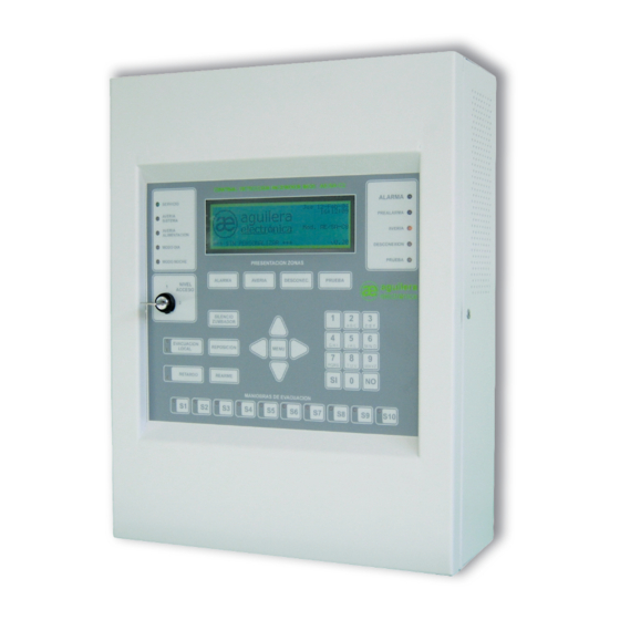
INSTALLATION GUIDE AE/SA-C1 8 SPECIFICATIONS. AE/SA-C1 Panel Specifications. Cabinet: Dimensions: Width: 320 mm. Height: 280 mm. Depth: 123 mm. Material: Sheet metal AP 011 Colour: RAL9002 Weight: Without batteries 4.5 Kg With two 12V/7Ah batteries 9.5 Kg Operational range: Temperature 0°... - Page 42 INSTALLATION GUIDE AE/SA-C1 Indicators: Graphic display 240 * 64 pixels, back-lit Lights Service System Fault Power Supply Fault Day Mode Night Mode Pre-alarm Alarm Fault Disconnection Test Local Evacuation (Alarm and fault) Delay Operation Sequences (10 indicators) Acoustic indicator Continuous in alarm state...
- Page 43 INSTALLATION GUIDE AE/SA-C1 Incident history Memory type Non-volatile RAM No. of incidents stored > 4,000 incidents Date and time of incidence Real-time clock Presentation Screen or printer Incident search by date Complete Alarms Faults Disconnections Tests Messages Access levels (according to EN54-2):...
- Page 44 Certificate: Aguilera Electrónica S.L. C/Julián Camarillo 26 - 28037 MADRID - SPAIN 0099/CPD/A74/0159 AE/SA-C1 ALGORITHMIC FIRE DETECTION PANEL EN 54-2:1997/A1:2006 Control and communication device for fire detection and alarm systems for buildings. EN54-4:1997/A2:2006 Power supply device for fire detection and alarm systems for buildings.
-
Page 45: Installation Registration Form
INSTALLATION GUIDE AE/SA-C1 INSTALLATION REGISTRATION FORM. DATE:_________________________ NAME (PROPERTY):________________________________________________________ ADDRESS:________________________________________________________________ TELEPHONE NO.:_____________________ PERSON RESPONSIBLE:___________________________________DATE:___________ PERSON RESPONSIBLE:___________________________________DATE:___________ PERSON RESPONSIBLE:___________________________________DATE:___________ PERSON RESPONSIBLE:___________________________________DATE:___________ ___________________________________________________________________________ INSTALLING COMPANY:_______________________________________________________ TECHNICIAN RESPONSIBLE: __________________________________________________ TELEPHONE NO.:____________________________________________________________ ___________________________________________________________________________ MAINTENANCE COMPANY:____________________________________________________ MAINTENANCE CONTRACT No.: _______________________________________________ TELEPHONE NO:_____________________________________________________________ VALID UNTIL:________________________________________________________________ Ae-man-851-0.0 v1.0... - Page 46 INSTALLATION GUIDE AE/SA-C1 INCIDENT RECORD DATE TIME INCIDENT ACTION SIGNATURE Ae-man-851-0.0 v1.0 AGUILERA ELECTRONICA...
- Page 48 YOUR NEAREST POINT OF ASSISTANCE AND SUPPLY CENTRAL OFFICE C/ Julián Camarillo, 26 – 2ª Planta – 28037 Madrid Tel: 91 754 55 11 GAS PROCESSING PLANT Av. Alfonso Peña Boeuf, 6. Pol. Ind. Fin de Semana – 28022 Madrid Tel: 91 754 55 11 NORTHEAST OFFICE C/ Rafael de Casanovas, 7 y 9 –...
Need help?
Do you have a question about the AE/SA-C1 and is the answer not in the manual?
Questions and answers