Table of Contents
Advertisement
Quick Links
Doc.-Nr.:
User & Installation manual
DE-3000-800100e
VHF- Communication Transceiver
Revision 13.0
KRT2, KRT2M, KRT2RC
Jul. 2016
KRT2, KRT2"Mini", KRT2RC
VHF Communication
Transceiver
P/N 100-(0XXX)-( ) KRT2
P/N 100-(1XXX)-( ) KRT2MH
P/N 100-(2XXX)-( ) KRT2MV
P/N 110-( )-( ) KRT2RC
Operation and Installation Manual
1 / 67
Advertisement
Table of Contents

Summary of Contents for TQ AirPlus KRT2 Series
- Page 1 Doc.-Nr.: User & Installation manual DE-3000-800100e VHF- Communication Transceiver Revision 13.0 KRT2, KRT2M, KRT2RC Jul. 2016 KRT2, KRT2”Mini”, KRT2RC VHF Communication Transceiver P/N 100-(0XXX)-( ) KRT2 P/N 100-(1XXX)-( ) KRT2MH P/N 100-(2XXX)-( ) KRT2MV P/N 110-( )-( ) KRT2RC Operation and Installation Manual 1 / 67...
- Page 2 Extension for Mini & Portrait 12.0 Oct. 2015 Updated part number and added EASA approval number. Included KRT2 Mini and Remote Control information. 13.0 July 2016 Included TQ references for customer support. Improvement of Self-Testing Diagnose Code 2 / 67...
- Page 3 Doc.-Nr.: User & Installation manual DE-3000-800100e VHF- Communication Transceiver Revision 13.0 KRT2, KRT2M, KRT2RC Jul. 2016 List of Service-Bulletins (SB) Service-Bulletins have to be inserted in the manual, and entered in the table. Rev. Date SB Number Date Issued Name Inserted Unit overview Item No.
-
Page 4: Table Of Contents
Doc.-Nr.: User & Installation manual DE-3000-800100e VHF- Communication Transceiver Revision 13.0 KRT2, KRT2M, KRT2RC Jul. 2016 TABLE OF CONTENTS GENERAL ............................7 Symbols ............................7 Acronyms ............................8 Customer Service ......................... 9 KRT2 Transceiver properties ......................9 Installation limitation ........................... 10 Installation ........................... - Page 5 Doc.-Nr.: User & Installation manual DE-3000-800100e VHF- Communication Transceiver Revision 13.0 KRT2, KRT2M, KRT2RC Jul. 2016 Electrical Connections ........................ 42 6.6.1 Microphone-Connection ...................... 42 6.6.2 Speaker & open microphone: ..................... 44 6.6.3 Earphone Connection ......................44 6.6.4 External Audio Input ......................44 6.6.5 Speaker Connection ......................
- Page 6 Doc.-Nr.: User & Installation manual DE-3000-800100e VHF- Communication Transceiver Revision 13.0 KRT2, KRT2M, KRT2RC Jul. 2016 Table of Figures Figure 1: Acronyms............................8 Figure 2: KRT2 Front view .......................... 12 Figure 3: KRT2Mini Front view ........................13 Figure 4: KRT2 Controls ..........................14 Figure 5: KRT2 Display..........................
-
Page 7: General
Doc.-Nr.: User & Installation manual DE-3000-800100e VHF- Communication Transceiver Revision 13.0 KRT2, KRT2M, KRT2RC Jul. 2016 1 GENERAL This manual contains information about the physical, mechanical and electrical properties as well as a description for the operation and installation of the VHF airborne transceiver KRT2. 1.1 Symbols WARNING Non-compliance may cause personnel injury due to radiation... -
Page 8: Acronyms
Doc.-Nr.: User & Installation manual DE-3000-800100e VHF- Communication Transceiver Revision 13.0 KRT2, KRT2M, KRT2RC Jul. 2016 1.2 Acronyms Description Definition Battery Check DC source Dimming Display brightness setting External audio input External Audio input level setting Intercom level Intercom volume level setting Push to Talk Transmitter activation The KRT2Rc is the KRT2 remote... -
Page 9: Customer Service
In order to process returned units most expeditiously, please use the email support.krt@tq-group.com website http://www.dittel- avionik.de/de/content/support. Suggestions which will improve this manual are very much appreciated at: info.dittel@tq-group.com. Information concerning software updates is available under support.krt@tq-group.com. 1.4 KRT2 Transceiver properties • VHF airborne transceiver • Frequency range 118,000 to 136,975 MHz •... -
Page 10: Installation Limitation
Doc.-Nr.: User & Installation manual DE-3000-800100e VHF- Communication Transceiver Revision 13.0 KRT2, KRT2M, KRT2RC Jul. 2016 Installation limitation The conditions and tests required for (E)TSO approval of this article are minimum performance standards. It is the responsibility of those installing this article either on or within a specific type or class of aircraft to determine that the aircraft installation conditions are within the (E)TSO standards. -
Page 11: Quantitative Safety Objective Identification
Doc.-Nr.: User & Installation manual DE-3000-800100e VHF- Communication Transceiver Revision 13.0 KRT2, KRT2M, KRT2RC Jul. 2016 2.3 Quantitative Safety Objective Identification In accordance with EASA regulations, the goal is a safety objective for the VHF COM radio in the KRT-2 VHF Communication Transceiver System of 1 x 10E-4 per flight hour for Class I Airplanes and 1 x 10E-5 per flight hour for Class II Airplanes. -
Page 12: Control General
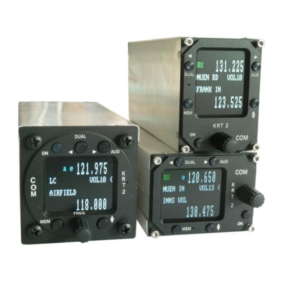
Doc.-Nr.: User & Installation manual DE-3000-800100e VHF- Communication Transceiver Revision 13.0 KRT2, KRT2M, KRT2RC Jul. 2016 CONTROL general 3.1 Control Elements Overview Figure 2: KRT2 Front view 12 / 67... -
Page 13: Figure 3: Krt2Mini Front View
Doc.-Nr.: User & Installation manual DE-3000-800100e VHF- Communication Transceiver Revision 13.0 KRT2, KRT2M, KRT2RC Jul. 2016 Figure 3: KRT2Mini Front view All functions and performances of the normal size unit (57mm round) and the Portrait format (Mini) are identical. The only differences are the text areas on the display Compare Figure 2: KRT2 Front view and Figure 3: KRT2Mini Front view for more details. -
Page 14: Figure 4: Krt2 Controls
Doc.-Nr.: User & Installation manual DE-3000-800100e VHF- Communication Transceiver Revision 13.0 KRT2, KRT2M, KRT2RC Jul. 2016 Function Usage Button ON / OFF Self-locking switch 1. Scanning between the Active and Standby frequencies DUAL WATCH 2. Positioning cursor to the left when programming the station identifier 1. -
Page 15: Display
Doc.-Nr.: User & Installation manual DE-3000-800100e VHF- Communication Transceiver Revision 13.0 KRT2, KRT2M, KRT2RC Jul. 2016 3.2 Display Indication Meaning Remarks RX is displayed during Reception reception (squelch opened) Transmitter operates Transmission normally Transmitter was turned off automatically after 2 min continuous operation 119.700 Active frequency... -
Page 16: Menu Levels
Doc.-Nr.: User & Installation manual DE-3000-800100e VHF- Communication Transceiver Revision 13.0 KRT2, KRT2M, KRT2RC Jul. 2016 Indication Meaning Remarks Supply voltage is low Low or defective battery / generator. <10,5V A-match Antenna error Bad antenna match a = AUX. Input active Status of certain Audio v = VOX active a v e... -
Page 17: Self-Test Error Reports
Doc.-Nr.: User & Installation manual DE-3000-800100e VHF- Communication Transceiver Revision 13.0 KRT2, KRT2M, KRT2RC Jul. 2016 3.4 Self-test error reports Display Meaning Remark Return the transceiver for Internal error, no Er_PLL maintenance transmission Return the transceiver for Internal error, Er_ADC maintenance operation limited Return the transceiver for... -
Page 18: Operation
Doc.-Nr.: User & Installation manual DE-3000-800100e VHF- Communication Transceiver Revision 13.0 KRT2, KRT2M, KRT2RC Jul. 2016 4 OPERATION 4.1 General In the normal operating mode in which the turning knob always is connected to the volume (VOL). The normal operating mode can be left by pressing the AUD, FREQ or MEMORY button. -
Page 19: Frequency Selection
Doc.-Nr.: User & Installation manual DE-3000-800100e VHF- Communication Transceiver Revision 13.0 KRT2, KRT2M, KRT2RC Jul. 2016 4.3 Frequency Selection There are two different frequency selection methods: • Direct Input • Selection from the favorite list (index 0-99) 4.3.1 Direct Frequency Selection The Standby-Frequency is set with the turning knob in 3 different ranges. -
Page 20: Frequency Selection From The Favorites List
Doc.-Nr.: User & Installation manual DE-3000-800100e VHF- Communication Transceiver Revision 13.0 KRT2, KRT2M, KRT2RC Jul. 2016 4.3.2 Frequency Selection from the Favorites List By pressing and operating the turning knob a specific favorite list position can be accessed [xx] (xx = index 0 … 99). When frequency and station identifier have been defined, they will be displayed in the Standby and station identifier windows. - Page 21 Doc.-Nr.: User & Installation manual DE-3000-800100e VHF- Communication Transceiver Revision 13.0 KRT2, KRT2M, KRT2RC Jul. 2016 In the identifier window a blinking cursor will show up under the extreme left character. The turning knob selects the desired character. The AUD button positions the curser one character to the right.
- Page 22 Doc.-Nr.: User & Installation manual DE-3000-800100e VHF- Communication Transceiver Revision 13.0 KRT2, KRT2M, KRT2RC Jul. 2016 When activated all 99 favorites will be sorted in alphabetical order and the process can take several minutes. During the sorting procedure “RUN nn“ is displayed in the program window, with nn being the running index.
-
Page 23: Aud - Audio Menu
Doc.-Nr.: User & Installation manual DE-3000-800100e VHF- Communication Transceiver Revision 13.0 KRT2, KRT2M, KRT2RC Jul. 2016 4.4 AUD – Audio Menu Any action in the Audio Menu requires the pointer (<) to be next to the Audio menu window (see picture). When the pointer next Standby... -
Page 24: Vox - Intercom Voice Trigger Level Setting
Doc.-Nr.: User & Installation manual DE-3000-800100e VHF- Communication Transceiver Revision 13.0 KRT2, KRT2M, KRT2RC Jul. 2016 For engine driven airplanes an initial setting of 3-5 is recommended. For gliders a setting of 2 is recommended. The lower the Squelch level value the higher is the input sensitivity. -
Page 25: Txm - Ptt Switch Selection
Doc.-Nr.: User & Installation manual DE-3000-800100e VHF- Communication Transceiver Revision 13.0 KRT2, KRT2M, KRT2RC Jul. 2016 Deactivation of the intercom is done with an opened external microphone button (Ground connection to pin 12), this is indicated with an “e” on the display. -
Page 26: Dim - Display Brightness
Doc.-Nr.: User & Installation manual DE-3000-800100e VHF- Communication Transceiver Revision 13.0 KRT2, KRT2M, KRT2RC Jul. 2016 4.4.8 DIM – Display Brightness Pressing the AUD button six times enables the turning knob to set the display brightness. Range: 01 – 16 DIMnn The display consumption at 12V is 70mA max and 10mA min. -
Page 27: Sit - Side Tone
Doc.-Nr.: User & Installation manual DE-3000-800100e VHF- Communication Transceiver Revision 13.0 KRT2, KRT2M, KRT2RC Jul. 2016 SIT – Side tone 4.4.10 Pressing the AUD button eight times enables the turning knob to set the side tone volume (for gliders should be set to 01). Range: 1 –... - Page 28 Doc.-Nr.: User & Installation manual DE-3000-800100e VHF- Communication Transceiver Revision 13.0 KRT2, KRT2M, KRT2RC Jul. 2016 Menus L and R: By means of the turning knob the displayed microphone input channel amplifier gain (MIC-level 01 = low gain, 09 =high gain) can be selected individually.
- Page 29 Doc.-Nr.: User & Installation manual DE-3000-800100e VHF- Communication Transceiver Revision 13.0 KRT2, KRT2M, KRT2RC Jul. 2016 Menu Auto In the AUTO mode (up to software version 6.16 every 30 sec. then at transmission start) the left microphone impedance is measured. When a dynamic microphone is recognized, the left channel is switch to 11, the right channel is unaffected.
-
Page 30: Menu Lock
Doc.-Nr.: User & Installation manual DE-3000-800100e VHF- Communication Transceiver Revision 13.0 KRT2, KRT2M, KRT2RC Jul. 2016 Additional indications Additional indications for test purposes: RxS : RF receiver input level (from Automatic Gain Control) Ext : External audio input voltage ... -
Page 31: Dual Watch
Doc.-Nr.: User & Installation manual DE-3000-800100e VHF- Communication Transceiver Revision 13.0 KRT2, KRT2M, KRT2RC Jul. 2016 4.5 DUAL Watch Because the communication transceiver KRT2 contains only one receiver, DUAL watch is achieved by alternating between the Active and Standby frequencies. The DUAL button activates and deactivates the dual watch function. -
Page 32: Figure 9: Krt2 Active & Standby Frequencies
Doc.-Nr.: User & Installation manual DE-3000-800100e VHF- Communication Transceiver Revision 13.0 KRT2, KRT2M, KRT2RC Jul. 2016 The pointer next to the DUAL display indicates on which frequency there is reception. Standby-frequency-reception Active-frequency-reception Figure 9: KRT2 Active & Standby frequencies Standby and Active frequencies can be exchanged when in the DUAL mode. -
Page 33: Transmitter Operation
Doc.-Nr.: User & Installation manual DE-3000-800100e VHF- Communication Transceiver Revision 13.0 KRT2, KRT2M, KRT2RC Jul. 2016 4.6 Transmitter Operation The unit transmits on the active frequency (upper line) as long as a PTT (press to talk) switch is pressed. Transmission Reception Figure 10: KRT2 TX &... -
Page 34: Two Ptt Configuration
Doc.-Nr.: User & Installation manual DE-3000-800100e VHF- Communication Transceiver Revision 13.0 KRT2, KRT2M, KRT2RC Jul. 2016 4.6.1 Two PTT Configuration There are two different PTT assigned for each of the left and right side microphones. This enables the deactivation of the unused one preventing additional noise and unintentional talking on transmission. -
Page 35: Optical Side Tone
Doc.-Nr.: User & Installation manual DE-3000-800100e VHF- Communication Transceiver Revision 13.0 KRT2, KRT2M, KRT2RC Jul. 2016 4.6.3 Optical side tone Especially when used in gliders, where headsets are generally not worn and thus no side tone is heard, it is very helpful to see if the microphone is operating properly. -
Page 36: Resetting To Factory Settings
Doc.-Nr.: User & Installation manual DE-3000-800100e VHF- Communication Transceiver Revision 13.0 KRT2, KRT2M, KRT2RC Jul. 2016 4.7 Resetting to factory settings Returning to the factory settings can only be initiated during power-up. To do this, during power-up the MEM and DUAL buttons must be pressed simultaneously and the display will show “SET DEFAULTS”. -
Page 37: Erase - Erasing The Favorites List
Doc.-Nr.: User & Installation manual DE-3000-800100e VHF- Communication Transceiver Revision 13.0 KRT2, KRT2M, KRT2RC Jul. 2016 4.8.1 ERASE – Erasing the Favorites List When in the SET UP – Menu select the “ERASE“ sub-menu with the buttons next to the symbols (Exit, Y). Erasing the favorites (frequency and identifier) starts after the button has been pressed again. -
Page 38: Remote Control
Doc.-Nr.: User & Installation manual DE-3000-800100e VHF- Communication Transceiver Revision 13.0 KRT2, KRT2M, KRT2RC Jul. 2016 5 Remote Control Tandem-seat airplanes can be equipped with the KRT2RC Remote Control Unit. The remote control unit is connected to RS232 serial interface and enables selection of the most common settings like frequency, volume, squelch, VOX, display contrast and brightness. -
Page 39: Installation
Doc.-Nr.: User & Installation manual DE-3000-800100e VHF- Communication Transceiver Revision 13.0 KRT2, KRT2M, KRT2RC Jul. 2016 6 Installation 6.1 Installation Hints The following hints should be considered for installation. A certified maintenance shop should perform the installation and wiring (or as required by local national regulations). -
Page 40: Telecommunication Data
Doc.-Nr.: User & Installation manual DE-3000-800100e VHF- Communication Transceiver Revision 13.0 KRT2, KRT2M, KRT2RC Jul. 2016 6.2 Telecommunication Data The following data may be required for the radio station licence application. Manufacturer AIRplus Maintenance GmbH Type KRT2 EASA Number EASA.21O.10058303 P/N 100-(0XXX)-(XXX) KRT2 P/N 110-(XXXX)-(XXX) KRT2RC Part Number... -
Page 41: Unpacking And Inspecting The Equipment
Doc.-Nr.: User & Installation manual DE-3000-800100e VHF- Communication Transceiver Revision 13.0 KRT2, KRT2M, KRT2RC Jul. 2016 6.4 Unpacking and Inspecting the Equipment Carefully unpack the equipment. Damages due to transportation must immediately be reported to the shipping company. Save the shipping container and all packing material to substantiate your claim. -
Page 42: Electrical Connections
Doc.-Nr.: User & Installation manual DE-3000-800100e VHF- Communication Transceiver Revision 13.0 KRT2, KRT2M, KRT2RC Jul. 2016 6.6 Electrical Connections The 15-pin D-Sub connector contains all electrical connections except the antenna. The battery plus connection must be protected with at least 3-amps slow blow fuse! 6.6.1 Microphone-Connection Both the L (left) and R (right) microphone input channels can either be... -
Page 43: Figure 13: Head Sets
Doc.-Nr.: User & Installation manual DE-3000-800100e VHF- Communication Transceiver Revision 13.0 KRT2, KRT2M, KRT2RC Jul. 2016 When the AUTO mode is selected in the MIC-Setup menu the KRT2 automatically recognizes on MIC-L (pin 3) which microphone type has been switched and acts accordingly. Both inputs (L and R) must not be wired together. -
Page 44: Speaker & Open Microphone
Doc.-Nr.: User & Installation manual DE-3000-800100e VHF- Communication Transceiver Revision 13.0 KRT2, KRT2M, KRT2RC Jul. 2016 6.6.2 Speaker & open microphone: An installation with open microphone together with a speaker and intercom is not possible. Running a speaker together with an open microphone (goose neck) the Intercom operation hast to be turned off by setting VOX=10 or opening the intercom switch (indicating “e”) otherwise a feedback from the speaker will occur. -
Page 45: Final Audio-Setup
Doc.-Nr.: User & Installation manual DE-3000-800100e VHF- Communication Transceiver Revision 13.0 KRT2, KRT2M, KRT2RC Jul. 2016 After turn on it will appear this warning on the screen in case the speaker is grounded. Running under that condition may cause a defect. 6.7 Final Audio-Setup This is an overview for a correct audio set up depending on the usage. -
Page 46: For Motor Gliders Dual Seaters
Doc.-Nr.: User & Installation manual DE-3000-800100e VHF- Communication Transceiver Revision 13.0 KRT2, KRT2M, KRT2RC Jul. 2016 6.7.2 For motor gliders dual seaters For change mode (motoring & headset – gliding & dynamic microphone) Press button AUD 3x for VOX: o Set to VOX 3. -
Page 47: Wiring
Doc.-Nr.: User & Installation manual DE-3000-800100e VHF- Communication Transceiver Revision 13.0 KRT2, KRT2M, KRT2RC Jul. 2016 6.8 Wiring 6.8.1 Wire Gauges Supply lines (Power, GND): AWG18 (0,83 mm²) Control lines: AWG22 (0,38 mm²) All wires must be aviation certified. 6.8.2 Connector Pin-Configuration Figure 14: Connector pin out If manual intercom is not used, pin 12 should be grounded. -
Page 48: General Hint
Doc.-Nr.: User & Installation manual DE-3000-800100e VHF- Communication Transceiver Revision 13.0 KRT2, KRT2M, KRT2RC Jul. 2016 Figure 15: Remote control pin out The nine pins connector on the KRT2RC is used for the connection to the KRT2. 6.8.3 General hint The following drawings are not covering all possible configurations. -
Page 49: Wiring Diagram
Doc.-Nr.: User & Installation manual DE-3000-800100e VHF- Communication Transceiver Revision 13.0 KRT2, KRT2M, KRT2RC Jul. 2016 6.8.4 Wiring Diagram 6.8.4.1 Two place motor aircraft connection Microphone-Setup: set L / R as required for headset, do not leave in AUTO 49 / 67... -
Page 50: Glider Two Place Connection
Doc.-Nr.: User & Installation manual DE-3000-800100e VHF- Communication Transceiver Revision 13.0 KRT2, KRT2M, KRT2RC Jul. 2016 6.8.4.2 Glider two place connection Microphone-Setup: leave in L =11, (not AUTO) 50 / 67... -
Page 51: Glider Single
Doc.-Nr.: User & Installation manual DE-3000-800100e VHF- Communication Transceiver Revision 13.0 KRT2, KRT2M, KRT2RC Jul. 2016 6.8.4.3 Glider single Microphone-Setup: leave with L =11 for dynamic, (not AUTO) 51 / 67... -
Page 52: Motor Glider Single
Doc.-Nr.: User & Installation manual DE-3000-800100e VHF- Communication Transceiver Revision 13.0 KRT2, KRT2M, KRT2RC Jul. 2016 6.8.4.4 Motor glider single Microphone-Setup: For Electret set L / R as required for headset, do not leave in AUTO-mode. For Dynamic, use a switch to cut off the dynamic mic. (If motoring) and leave setup in AUTO-mode, wire PTT-L and PTT-R in parallel. -
Page 53: Motor Glider Dual-Dynamic Microphone
Doc.-Nr.: User & Installation manual DE-3000-800100e VHF- Communication Transceiver Revision 13.0 KRT2, KRT2M, KRT2RC Jul. 2016 6.8.4.5 Motor glider dual-Dynamic Microphone Dynamic Microphone Microphone-Setup: R for headsets, leave menu in AUTO mode. 53 / 67... -
Page 54: Motor Glider Dual-Electret Microphone
Doc.-Nr.: User & Installation manual DE-3000-800100e VHF- Communication Transceiver Revision 13.0 KRT2, KRT2M, KRT2RC Jul. 2016 6.8.4.6 Motor glider dual-Electret Microphone Electret Microphone Microphone-Setup: leave L = 3..9 (in case of dynamic =11), R=3 (not AUTO-mode). 54 / 67... -
Page 55: Wiring For Dynamic Microphones
Doc.-Nr.: User & Installation manual DE-3000-800100e VHF- Communication Transceiver Revision 13.0 KRT2, KRT2M, KRT2RC Jul. 2016 6.8.5 Wiring for dynamic microphones Special attention is required for the wiring for dynamic microphones. Because of the required high gain any mistake on the ground wiring leads to interferences and feed backs. -
Page 56: Antenna
Doc.-Nr.: User & Installation manual DE-3000-800100e VHF- Communication Transceiver Revision 13.0 KRT2, KRT2M, KRT2RC Jul. 2016 6.9 Antenna 6.9.1 Antenna Selection A 50 Ohms impedance VHF-COM-antenna is required. The antenna must be approved in respect to aircraft type and installation location. -
Page 57: Microphone General
Doc.-Nr.: User & Installation manual DE-3000-800100e VHF- Communication Transceiver Revision 13.0 KRT2, KRT2M, KRT2RC Jul. 2016 6.10 Microphone general The correct setting of the MIC and VOX values is of great importance for the Intercom system (see “4.4.3 VOX – Intercom Voice Trigger Level Setting”... -
Page 58: Post-Installation Check
Doc.-Nr.: User & Installation manual DE-3000-800100e VHF- Communication Transceiver Revision 13.0 KRT2, KRT2M, KRT2RC Jul. 2016 6.11 Post-Installation Check A certified maintenance shop must verify the proper operation of the VHF transceiver or as required by national regulations. A complete check of all airplane systems is required to certify that the new wiring is not causing any malfunction. -
Page 59: Accessories
Doc.-Nr.: User & Installation manual DE-3000-800100e VHF- Communication Transceiver Revision 13.0 KRT2, KRT2M, KRT2RC Jul. 2016 6.13 Accessories Suitable accessories such as antennas, cable sets, and switches can be purchased at our online shop on http://www.dittel-avionik.de or from other avionics suppliers. 59 / 67... -
Page 60: Drawings
Doc.-Nr.: User & Installation manual DE-3000-800100e VHF- Communication Transceiver Revision 13.0 KRT2, KRT2M, KRT2RC Jul. 2016 6.14 Drawings 6.14.1 Dimensions Figure 17: KRT2 Dimensions Figure 18: KRT2M “Mini” Dimensions 60 / 67... -
Page 61: Figure 19: Krt2Rc Remote Control Dimensions
Doc.-Nr.: User & Installation manual DE-3000-800100e VHF- Communication Transceiver Revision 13.0 KRT2, KRT2M, KRT2RC Jul. 2016 Figure 19: KRT2RC Remote Control Dimensions 61 / 67... -
Page 62: Installation Directions
Doc.-Nr.: User & Installation manual DE-3000-800100e VHF- Communication Transceiver Revision 13.0 KRT2, KRT2M, KRT2RC Jul. 2016 6.14.2 Installation Directions Connection Area Panel Cut-out Figure 20: KRT2 Panel Cut out Figure 21: KRT2M “Mini” Panel Cut out 62 / 67... -
Page 63: Maintenance
Doc.-Nr.: User & Installation manual DE-3000-800100e VHF- Communication Transceiver Revision 13.0 KRT2, KRT2M, KRT2RC Jul. 2016 7 Maintenance 7.1 Periodic Maintenance There are no scheduled service tasks required on the KRT-2 VHF unit. 7.2 Repair Only exchange and flat repair of the equipment is permitted. In case of equipment failure, the unit must be sent to the manufacturer. -
Page 64: Annex
Doc.-Nr.: User & Installation manual DE-3000-800100e VHF- Communication Transceiver Revision 13.0 KRT2, KRT2M, KRT2RC Jul. 2016 8 ANNEX 8.1 Frequency / Channel- schedule The following table contains the operating and displayed frequencies between 118.000 and 118.100MHz. The table can be continued up to 136.975 MHz following the same principle. -
Page 65: Technical Data
Doc.-Nr.: User & Installation manual DE-3000-800100e VHF- Communication Transceiver Revision 13.0 KRT2, KRT2M, KRT2RC Jul. 2016 8.2 Technical Data GENERAL Approval Number ETSO_21O.10058303 ETSO-2C169a / TSO-C169a Transmitter: Compliance ED-23C Class 4,6 / DO-186B, Class 4,6 Standards Receiver: ED-23C Class C-D-E-H1/2 / DO-186B, Class C-D-E EUROCAE ED-23C / RTCA DO-186B RTCA DO-160F/ED14F Standards... -
Page 66: Figure 23: Technical Data
Doc.-Nr.: User & Installation manual DE-3000-800100e VHF- Communication Transceiver Revision 13.0 KRT2, KRT2M, KRT2RC Jul. 2016 GENERAL 9 VDC to 33VDC test @ 13.8VDC Transmitter: 2.0 A (typ.) Receiver: 0.13 A Power Supply Illumination 0.01A to 0.07A ... -
Page 67: Figure 24: Transmitter/Receiver
Doc.-Nr.: User & Installation manual DE-3000-800100e VHF- Communication Transceiver Revision 13.0 KRT2, KRT2M, KRT2RC Jul. 2016 TRANSMITTER 6 W (nominal) @ >13.5V Power Output 4 W (minimal) Harmonic Distortion <10 % at 70 % modulation Sidetone Output >0,5W an 300Ω (head set output) 2 x standard (50mV…2V) into 100Ω...
Need help?
Do you have a question about the AirPlus KRT2 Series and is the answer not in the manual?
Questions and answers