Table of Contents
Advertisement
iC-TW29
26-BIT ENCODER PROCESSOR
WITH INTERPOLATION AND BiSS INTERFACE
FEATURES
Any output resolution with any input resolution
•
Independently-programmed ABZ, UVW, and BiSS resolutions
•
Absolute data interface for external revolution counters
•
BiSS C-Mode interface (Encoder Profiles 3, 3S, and 4)
•
26-bit singleturn position and 32-bit revolution count via SPI
•
Four capture registers for coded reference marks and
•
touch-probe applications
Eccentricity compensation
•
Input frequency up to 700 kHz
•
AB output frequency of up to 12.5 MHz
•
Differential RS422 line driver outputs for ABZ or UVW
•
Simultaneous single-ended outputs for ABZ, UVW, BiSS
•
Automatic compensation of amplitude, offset, and phase errors
•
Digital filtering for ultra-low output jitter
•
Encoder Link interface for in-field re-configuration
•
Internal EEPROM and oscillator
•
LED intensity control by PWM output
•
Low latency (2.4 µs or 5.0 µs)
•
Pin-compatible with iC-TW28
•
BLOCK DIAGRAM
AVDD
AVSS
SIN+
SIN–
Interpolator
COS+
COS–
ZERO+
ZERO
ZERO–
Channel
iC-TW29
xSS
SCK
SPI
SO
Interface
SI
Copyright © 2019, 2020 iC-Haus
Interpolated Angle (IA)
26-Bit
Gearbox
Zero Gating Window (ZW)
Includes
Filter,
Hysteresis,
and
Eccentricity
Correction
Revolution Count (RC),
Cycle Count (CC), and Sync Bits
Monitors:
Status/Fault, Temp.,
Sin/Cos Amplitude,
Excessive Error,
Excessive Adaption
xIRQ
APPLICATIONS
•
•
•
•
PACKAGES
DVDD
DVSS
Normalized Angle (NR)
Output Freq.
Revolution Count (RC)
IA
Position
CC
Capture
RC
BiSS Slave
with Encoder
Profile and
UVW Scan
Absolute Data
Auto Calibration,
Auto Adaption,
Encoder Link
LED Control, Startup,
ID, EEPROM
xCALIB
LED
Rev C1, Page 1/28
Rotary and linear incremental or
absolute encoders
Magnetic or optical sin/cos
sensor interface
Brushless motor commutation
(2...64 poles)
Imbedded motion control
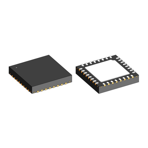
32-pin QFN
5 mm x 5 mm x 0.9 mm
RoHS compliant
IOVDD
IOVSS
ABZ with
Limiter
UVW
EDS
I/O
Multiplexer
Interface
(ADI)
http://www.ichaus.com
A+
A–
B+
B–
Z+
Z–
GPIO
Advertisement
Table of Contents

Summary of Contents for iC-Haus iC-TW29
- Page 1 Absolute Data Cycle Count (CC), and Sync Bits Interface (ADI) Monitors: GPIO Auto Calibration, Status/Fault, Temp., Auto Adaption, Sin/Cos Amplitude, Encoder Link Interface LED Control, Startup, Excessive Error, ID, EEPROM Excessive Adaption xIRQ xCALIB Copyright © 2019, 2020 iC-Haus http://www.ichaus.com...
- Page 2 EDS. mutation (UVW) outputs separately or in combination. Extensive status/fault and signal quality monitoring The iC-TW29 accepts 20 mV to 2 V differential sin/- capabilities allow detection and notification of poor cos input signals directly from magnetic or optical operating conditions.
-
Page 3: Table Of Contents
26-BIT ENCODER PROCESSOR WITH INTERPOLATION AND BiSS INTERFACE Rev C1, Page 3/28 CONTENTS PACKAGING INFORMATION Reference Outputs ....PIN CONFIGURATION QFN32-5x5 .. -
Page 4: Packaging Information
26-BIT ENCODER PROCESSOR WITH INTERPOLATION AND BiSS INTERFACE Rev C1, Page 4/28 PACKAGING INFORMATION (Compatible with iC-TW28) PIN CONFIGURATION QFN32-5x5 PIN FUNCTIONS No. Name Function 1 SIN+ + Differential Sine Input 2 SIN– – Differential Sine Input 3 AVDD +3.3 V Analog Power Supply Input... -
Page 5: Package Dimensions
26-BIT ENCODER PROCESSOR WITH INTERPOLATION AND BiSS INTERFACE Rev C1, Page 5/28 PACKAGE DIMENSIONS RECOMMENDED PCB-FOOTPRINT 4.90 3.60 SIDE 0.50 0.30 BOTTOM 3.65 0.50 0.22 All dimensions given in mm. Tolerances of form and position according to JEDEC MO-220. -
Page 6: Pin Functions
26-BIT ENCODER PROCESSOR WITH INTERPOLATION AND BiSS INTERFACE Rev C1, Page 6/28 PIN FUNCTIONS No. Name Function Description SIN+ Analog in Sine Input + Differential sine signal input. For single ended sensors SIN– must be biased to an appropriate DC level. - Page 7 26-BIT ENCODER PROCESSOR WITH INTERPOLATION AND BiSS INTERFACE Rev C1, Page 7/28 PIN FUNCTIONS No. Name Function Description Digital in SPI Slave Input Connect to SPI master MO pin. SCLK Digital in SPI Slave Clock Input Connect to SPI master clock output pin.
-
Page 8: Absolute Maximum Ratings
26-BIT ENCODER PROCESSOR WITH INTERPOLATION AND BiSS INTERFACE Rev C1, Page 8/28 ABSOLUTE MAXIMUM RATINGS These ratings do not imply operating conditions; functional operation is not guaranteed. Beyond these values damage may occur. Item Symbol Parameter Conditions Unit Min. -
Page 9: Electrical Characteristics
26-BIT ENCODER PROCESSOR WITH INTERPOLATION AND BiSS INTERFACE Rev C1, Page 9/28 ELECTRICAL CHARACTERISTICS Operating conditions: AVDD = DVDD = IOVDD = 3.1...3.6 V, Tj = –40...+125 °C, reference point AVSS unless otherwise stated Item Symbol Parameter Conditions Unit Min. - Page 10 26-BIT ENCODER PROCESSOR WITH INTERPOLATION AND BiSS INTERFACE Rev C1, Page 10/28 ELECTRICAL CHARACTERISTICS Operating conditions: AVDD = DVDD = IOVDD = 3.1...3.6 V, Tj = –40...+125 °C, reference point AVSS unless otherwise stated Item Symbol Parameter Conditions Unit Min.
- Page 11 26-BIT ENCODER PROCESSOR WITH INTERPOLATION AND BiSS INTERFACE Rev C1, Page 11/28 ELECTRICAL CHARACTERISTICS Operating conditions: AVDD = DVDD = IOVDD = 3.1...3.6 V, Tj = –40...+125 °C, reference point AVSS unless otherwise stated Item Symbol Parameter Conditions Unit Min.
- Page 12 26-BIT ENCODER PROCESSOR WITH INTERPOLATION AND BiSS INTERFACE Rev C1, Page 12/28 Maximum Input Voltage AVDD AVDD SIN+% Maximum COS+% Maximum Input Voltage Input 2.2 V SIN–% Amplitude (2 V) COS–% Max. Input SIN+% COS+% Amplitude SIN–% COS–% (700 mV) 1.0 V...
-
Page 13: Operating Requirements Spi Interface
26-BIT ENCODER PROCESSOR WITH INTERPOLATION AND BiSS INTERFACE Rev C1, Page 13/28 OPERATING REQUIREMENTS: SPI Interface Operating conditions: AVDD = DVDD = IOVDD = +3.1...+3.6 V, AVSS = DVSS = IOVSS = 0 V, Tj = –40...125 °C Item... -
Page 14: Encoder Link Interface
T1 ±10% T1 ±10% T1 ±10% A– External driver starts to overpower iC- iC-TW29 stops driving A+ and A–. TW29 by forcing A+ and A– high. Encoder Link interface is now active. Figure 7: Encoder Link Activation Sequence T ELCLK(high) -
Page 15: Biss Interface
26-BIT ENCODER PROCESSOR WITH INTERPOLATION AND BiSS INTERFACE Rev C1, Page 15/28 OPERATING REQUIREMENTS: BiSS Interface Operating conditions: AVDD = DVDD = IOVDD = +3.1...+3.6 V, AVSS = DVSS = IOVSS = 0 V, Tj = –40...125 °C Item... -
Page 16: Adi Interface
26-BIT ENCODER PROCESSOR WITH INTERPOLATION AND BiSS INTERFACE Rev C1, Page 16/28 OPERATING REQUIREMENTS: ADI Interface Operating conditions: AVDD = DVDD = IOVDD = +3.1...+3.6 V, AVSS = DVSS = IOVSS = 0 V, Tj = –40...125 °C Item... -
Page 17: Functional Block Diagram
Figure 14: Functional Block Diagram The iC-TW29 uses a modular architecture as shown in The full absolute position value of the iC-TW29 can be Figure 14. captured and read out over the SPI port. This posi- tion capture takes place on the rising edge of the zero... - Page 18 UVW scan mode allows external UVW signals to be used, the residues allow sensor signal quality to be read by the iC-TW29 and sent to the BiSS master with monitored by a host processor. the BiSS single cycle data (BP4 or custom encoder pro- file only).
- Page 19 The Encoder Link interface provides read/write access are not enabled until the appropriate position (relative to the iC-TW29’s internal registers using the A+ and A– or absolute) is established. outputs in ABZ or UVW output modes. This is useful for...
-
Page 20: Electrical Connections
26-BIT ENCODER PROCESSOR WITH INTERPOLATION AND BiSS INTERFACE Rev C1, Page 20/28 ELECTRICAL CONNECTIONS The basic electrical connections for an incremental Application Hint stand-alone application with differential ABZ outputs The input voltages must not exceed the chip’s supply are shown in Figure 15. Other than the sin/cos sensor, voltage (3.3 V). - Page 21 26-BIT ENCODER PROCESSOR WITH INTERPOLATION AND BiSS INTERFACE Rev C1, Page 21/28 The basic electrical connections for an absolute mul- such as the TXS0104E, is required. An external mul- titurn stand-alone application using BiSS are shown titurn device, such as the iC-PVL, is connected to the in Figure 16.
-
Page 22: Power And Ground
(such as iC-LSHB or decoupled to ground with separate 100 nF capacitors iC-PT...H series) sensors providing differential sin/cos placed as close to the iC-TW29 as possible. VC should outputs, as shown in Figure 18 and Figure 19. -
Page 23: Zero Inputs
COS– Digital Hall active low Figure 20: Digital Index Sensor Connection Figure 18: Magnetic Sensor Connection Analog-output zero sensors, such as MR bridges, can also be used with the iC-TW29 as shown in Figure 21. iC-TW29 iC-PT…H iC-TW29 Sensor ZERO+ SIN+ SIN–... -
Page 24: Abz Outputs
120 Ω way, when a warning or fault occurs, the host processor Z– Z– can query the iC-TW29 to determine what action to take. xIRQ can also be configured as an external fault input. Figure 22: ABZ Output Connection xIRQ can be configured as an open-drain output allow-... -
Page 25: Spi Port
SPI Port If the host processor or microcontroller can be discon- The iC-TW29 provides a standard SPI (Serial Periph- nected, the SPI port pins must be pulled up or down as eral Interface) slave port that can be used for device shown in Figure 24. -
Page 26: Configuration And Calibration
EEPROM. Finally, restart need to be configured. For example, if ABZ outputs are the iC-TW29 by clicking the play button ( ) on the main not enabled, the ABZ output module does not need to GUI window. -
Page 27: Biss/Ssi Configuration
product. - Page 28 QFN32-5x5 thickness 0.9 mm, RoHS compliant ABZ Evaluation Board PCB, approx. 50 mm x 123 mm iC-TW29 EVAL TW29_1D and SPI Programmer BiSS Evaluation Board PCB, approx. 50 mm x 123 mm iC-TW29 EVAL TW29_3D iC-TW29 GUI Evaluation software for...
Need help?
Do you have a question about the iC-TW29 and is the answer not in the manual?
Questions and answers