Table of Contents
Advertisement
Advertisement
Table of Contents

Summary of Contents for 2VV Superior Master
- Page 1 FINESSE / STANDESSE SUPERIOR regulace EN Installation and operation instructions...
-
Page 2: Package Contents
CONTROL THE DELIVERY PACKAGE CONTENTS PLEASE NOTE Check the product for damages immediately after delivery In case damage on the packaging, contact the carrier Claims not filed in due time will be disregarded. Check that it corresponds to the type of product ordered. •... - Page 3 1. INSTALLATION 1.2 EXTERNAL ACCESSORIES SUPERIOR MASTER Regulation module Master Superior VCS-R2-SU-*- VCS-R2-SU-*- VCS-R2-SU-*- INPUT Entrée Control panel boitier de commande 0-10 24VAC ModBUS RTU via INPUT Entrée INPUT INPUT INPUT Rs485 INPUT Entrée Entrée Entrée Entrée Entrée Control panel...
- Page 4 1. INSTALLATION SUPERIOR MASTER Regulation module Slave SUPERIOR VCS-R2-SU-*- VCS-R2-SU-*- VCS-R2-SU-*- Control panel boitier de commande 0-10 24VAC ModBUS RTU via Rs485 23 24 25 26 49 50 EXT. SENSOR Capteur Externe. 24VAC 0-10V 24VAC MIX. POINT / OUTDOOR (two-wire shielded cable) POWER SUPPLY Câble deux fils blindé...
-
Page 5: Connecting External Accessories
2. EXTERNAL ACCESSORIES 2.1 CONNECTING EXTERNAL ACCESSORIES PLEASE NOTE The unit must be disconnected from the power supply to connect accessories. • All external control components must be connected according to the wiring diagram. • The connectors must be connected to the electrical board with adequate force and always perpendicular to the base. •... - Page 6 2. EXTERNAL ACCESSORIES 2.1-5 Room thermostat - TER-P TECHNICAL INFORMATION - Room thermostat to regulate heating – Cable - Two-core cable with a cross-section of 1.5 mm , 230 V/ 50 Hz. CAUTION! Not included with the product. 3. COMMISSIONING PLEASE NOTE Before starting up the unit, check the following: Did you leave inside tools or objects that could damage the unit?
-
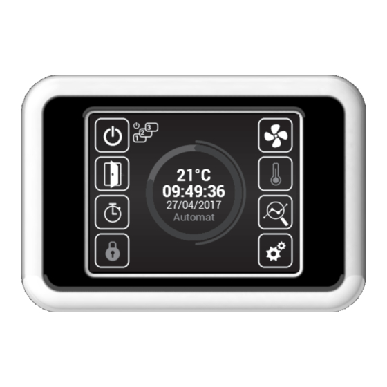
Page 7: Description Of Main Screen
4. CONTROL READ CAREFULLY! Before the initial commissioning, check: that the device is well fastened to the support structure, • that the device is properly closed • that the power supply is properly connected, including the earthing and the external trigger protection, •... - Page 8 4. CONTROL Current status This screen show the detailed status of the opening and the sensor values: • Current air-flow settings (step or %), information icons • Air temperature at intake*, exhaust*, room temperature* and outside temperature* (* – if the relevant sensors are installed and enabled) •...
- Page 9 4. CONTROL Timer Language Unless otherwise set, the unit goes on stand-by mode after the timer expires. There are 5 languages available Weekly mode Activate/deactivate timer Select lan- Annual mode guage Back to main Confirm screen + return Confirm Back to main screen + return Weekly mode Lightning settings...
-
Page 10: Service Menu
4. CONTROL Service menu MENU - HW SETTING Enter code 1616 to access the service menu Use this menu to set the detailed behaviour of the inputs and outputs of the regulators 1616 Door contact (NO/NC) Ad 1) Ad 2) External control contact (NO/NC) Ad 3) -
Page 11: Menu - Network
4. CONTROL MENU - FILTER TIMER MENU - OUTLET TEMP LIMITS Use this menu to set the period (in motor hours) after which Use this menu to set the limits of the exhaust you will be reminded to replace the filters or reset to timer. Set the time after which a notice will appear in Maximum temperature limit: 25°C... - Page 12 4. CONTROL MENU - USER LOCK Use this menu to set the limits to control the regulator with a Ventilation rate with open doors multi-level panel (20%-100%) Heating settings with open doors Limit level – see Ad1) Manual = 0%, 50%, 100% Auto = 15°C-45°C Enter PIN 0000~9999 (numeric values only)
- Page 13 4. CONTROL MENU - OTHER SETTINGS MENU - WATER ANTIFREEZE The menu is enabled only in units with water exchanger Use this menu to set the remaining parameters Settings (20%-100%) Enable/disable automatic switch of summer/winter time Ventilation rate with open doors Ad 1) –...
-
Page 14: Menu - Factory Reset
4. CONTROL Electric connection – Option 2: Electric connection – Option 2: MENU - FACTORY RESET Use this to reset the default values Press “FACTORY RESET” to reset the default values of MENU 1616 Once completed, we recommend to turn the main supply off and on. - Page 15 5. MALFUNCTIONS 5.1 MALFUNCTIONS Disconnect the main power supply before any intervention to the unit. If you are not sure of the correct steps, do not attempt to perform any repairs and call a professional service! Unit Description Likely problem Solution behaviour 44 –...
-
Page 16: Maintenance
7.1 IF YOU ARE UNABLE TO REPAIR THE UNIT If you were unable to solve a problem, contact the supplier or the representative of 2VV. Warranty and post-warranty service are provided by the supplier or an authorised service included in the list available at the supplier’s. -
Page 17: Wiring Diagram
8. WIRING DIAGRAM FUSE RELAY NTC 10K RELAY RELAY RELAY NTC 10K RELAY 25 26 27 28 29 30 63 64 65 66 +12V SLOT CANH CANL NTC 10K... - Page 18 8. WIRING DIAGRAM NTC 10K...
- Page 19 8. WIRING DIAGRAM NTC 10K FUSE RELAY NTC 10K RELAY RELAY NTC 10K RELAY RELAY 25 26 27 28 29 30 63 64 65 66 +12V SLOT CANH CANL...
- Page 20 8. WIRING DIAGRAM NTC 10K...
- Page 21 8. WIRING DIAGRAM FUSE NTC 10K RELAY NTC 10K RELAY RELAY RELAY RELAY 25 26 27 28 29 30 63 64 65 66 +12V SLOT CANH CANL...
- Page 22 8. WIRING DIAGRAM NTC 10K...
- Page 23 9. CONCLUSION 9. CONCLUSION In case of any doubt or query, do not hesitate to contact our sales or technical support departments. CONTACT Address: 2VV, s.r.o., Poděbradská 289, 530 09 Pardubice, Czech Republic Internet: http://www.2vv.cz/contact.distribution.php...
Need help?
Do you have a question about the Superior Master and is the answer not in the manual?
Questions and answers