Table of Contents
Advertisement
Quick Links
TECNICOMAR SYSTEM FOR SEWAGE WATER TREATMENT
UV Sterilization
Unit
Rev.
Date
00
10.02.2019
INSTRUCTIONS FOR THE INSTALLATION,
USE AND MAINTENANCE OF
MODEL: ECOmar 20 S; 32 S; 45 S; 70 S; 145 S.
Sludge
Valve
Multimedia
Filter Station
Image for illustration purposes only
Main Unit
ECOFLOC
Dosing
System
Main content revisions
S
Filling
Water
Pump
Pump
H
H
O
O
2
2
2
2
Sea
Dosing
Dosing
System
System
Advertisement
Table of Contents

Summary of Contents for TECNICOMAR ECOmar S Series
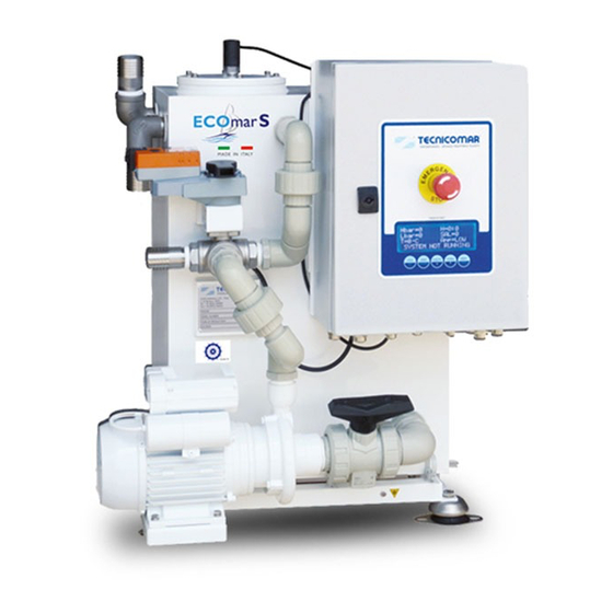
- Page 1 INSTRUCTIONS FOR THE INSTALLATION, USE AND MAINTENANCE OF TECNICOMAR SYSTEM FOR SEWAGE WATER TREATMENT MODEL: ECOmar 20 S; 32 S; 45 S; 70 S; 145 S. UV Sterilization Unit Sludge Valve Dosing Dosing Filling Water System System Pump Main Unit...
- Page 2 We would like to thank you for choosing a TECNICOMAR system to treat the sewage water. All TECNICOMAR equipments are designed by expert technicians and manufactured with care for all its aspects and in respect of the EU Directives for the machinery (safety) 89/392 and later modifications.
-
Page 3: Table Of Contents
TABLE OF CONTENTS INTRODUCTION ................................5 STORAGE PRIOR TO UNPACKING AND PACKAGING CONTENT ................ 5 Storage Prior to Unpacking ............................5 Unpacking ..................................5 Checking Packaging Content ............................5 MARKING OF PRUDOCT ............................... 6 PLACARD ..................................6 TREATMENT CAPACITY .............................. 6 SYSTEM DESCRIPTION .............................. - Page 4 15.4 ECOmar 70 S – Data Sheet ............................72 15.5 ECOmar 145 S – Data Sheet ............................73 SPARE PARTS LISTS ..............................74 WARRANTY FOR TECNICOMAR EQUIPMENTS ....................80 17.1 WARRANTY CLAIM ..............................80 17.1.1 ECOmar S - WARRANTY REGISTRATION CARD ................... 81...
-
Page 5: Introduction
After unpacking the Sewage Treatment Plant (STP), check all the parts for any damage. Claims for any missing or damaged materials must be made immediately to Tecnicomar authorized dealer or Tecnicomar headquarters In the package there are usually the following components: •... -
Page 6: Marking Of Prudoct
55000 ppm Salinity *System running 24 hours per day. **Indicative maximum persons number, at peak treatment capacity per day (system running 24h/24h). Ask to Tecnicomar S.P.A. for a proper plant sizing. ***Designed to operate in salt, brackish and fresh water. -
Page 7: System Description
6 SYSTEM DESCRIPTION The ECOmar S STP can be supplied with two different configuration: 1 Tank Control or 2 Tanks Control. The main differences between the two configurations are the number of the supplied filling pumps (1 or 2); the number of the supplied anti-syphon valve set;... - Page 8 Loose parts 2. An Additional Unit made by: 2.1. Nr.1 ECOFLOC Dosing System composed by a tank and a dosing pump; 2.2. Nr.1 Sludge Discharge Valve (V2) to divert the treated water to the multimedia filter station inlet or to the sludge tank; 2.3.
-
Page 9: Management System Of The Level Signals From The Collecting Tank Sensors
floats on the liquid free surface. In the treatment process, can be released some vapors which, if not correctly expelled from the treatment tank air vent, could bring to harmful overpressure inside the tank, damaging it. The Treatment Tank is designed to withstand a certain degree of internal overpressure. - Page 10 Max level When the collecting tank is empty, the level of sewage is below the minimum level and of course below the maximum level. The min level sensor has to give a closed free voltage contact signal to the ECOmar S main control box; and the max level sensor has to Min level give an open free voltage contact signal to the ECOmar S main control box.
-
Page 11: Control Box For Level Probe
Max level Closed Contact Min level IV.1. The sewage level inside the collecting tank is still above Open the minimum level. The min level probe installed on the Contact collecting tank, continues to give an open free voltage contact signal to the ECOmar S control box; and the max level sensor continues to give a closed free voltage contact signal to the ECOmar S main control box. - Page 12 level probe, ignore it if the system is supplied with the standard configuration). There is no light for the COMMON level related to the probe longer rod. The level probe manage the 3-rods level probe as to translate the level signals coming from it into the appropriate free voltage signals for the correct plant functioning.
-
Page 13: Safety Instructions
Nevertheless it is to remember that this manual is necessary but not enough to complete the training of the specialists that will operate the system, Tecnicomar is excluded from any contractual or extra contractual responsibility for damage caused to people, things or pet, after the improper use of the sewage treatment plant and non-observance of the norms and instructions contained in this manual. - Page 14 Dangers can be of three levels: WARNING The “WARNING” sign means that if the operations described are not well done they can cause heavy lesions, death or long term risks for health. The instructions should be followed carefully to operate the ECOmar S STP correctly. DANGER The sign “DANGER”...
-
Page 15: Ce Declaration Of Compliance
CE Declaration of Compliance The original copy of the CE Declaration of Compliance here reported in facsimile, is delivered along with the test report of the ECOmar S plant, in the annexes of this manual. Fig. 7.3 (Declaration of "CE" Conformity form) -
Page 16: Targets Of The Manual
He is capable of carry out complex operations on the system and in particular situations. SYSTEM MANAGER: Authorised and expert operator, trained by Tecnicomar technician on the working and maintenance of the system. He must be present during every work on the system as the only manager and must overview the observance of the accident prevention measures. -
Page 17: Protections
♦ The operations and/or procedures for use not recommended and/or indicated in the manual will always be notified to Tecnicomar for confirmation; ♦ If a not recommended procedure will be used, the user must check for safety of people, things and pet;... -
Page 18: Danger Informations
• Do not tamper with the components of the sewage treatment plant to obtain different performances than the ones expected from the manufacturer; • Do not wear fluttering clothes, rings and/or chains when working near moving parts; • Use protective gloves and glasses: During the use of chemical products (hydrogen peroxide solution 35%, or similar others). -
Page 19: Fire And Explosion Prevention
Fire and Explosion Prevention Most of the lubricants, disinfectant liquids and other chemicals solutions are inflammable. Spreading of these inflammable substances can cause fires. Put away lubricants in appropriate marked containers away from not authorised people. Put away soaked rags and inflammable materials in protective containers. Don’t smoke in areas used to keep inflammable materials. Do not expose the ECOmar S STP, especially the dosing systems, to any kind of flames. -
Page 20: Installation
8 INSTALLATION NOTE: This section concern only the standard supply configuration of the ECOmar S STP for the optional items installation, refer to the specific item manual. Components to be supplied by Owner* Some plumbing and electric components are to be supplied by owner. These components are listed below: a) On board sewage collecting tank;... -
Page 21: Installation Of The Level Sensor For Sludge Tank
(refer to attached G.A. drawings). Remember to leave enough room between the bulkheads and the installed skid and base- frames for the wiring, the pipeline and the future maintenance (a margin of at least 10 cm is suggested). For the correct maintenance space of the plant refer to the specific attached G.A. -
Page 22: Installing The Air Relief
The installation of the level sensor on the top of the collecting tank should be done by qualified technicians. The standard supplied Level Probe consists of 3 coated electrodes (if it is require TECNICOMAR S.P.A. - Page 23 In this way, the system will work correctly and its performances will be optimized (few continuous cycles). Fig. 8.6.1.1-1 - Collecting tank and 3-rods level sensor Hints for rods cutting: • While cutting one rod, take care not to damage the isolation of the others. •...
-
Page 24: Installing Filling Pump
As alternative to the rods Level Probe, it is possible to install no. 2 (even 3 when is required alarm for Absolute Maximum level) lateral mounting level probes. In this case the collecting tank must be prepared with 2 (or 3 in case of absolute maximum alarm) ½”... -
Page 25: Installation Of The Suction Pipe Of The Filling Pump
The pump should be bolted to a firm, flat base in a dry, well ventilated area. If mounted outside, it is recommended that the motor be protected from the elements with a well ventilated weather proof cover. If mounted near walls, it is recommended a distance of at least 100mm between the suction grid of the cooling fan of the motor and the wall. -
Page 26: Installing H
When the liquid level on the suction side is above the pump (inflow positive suction head), install the sea water anti siphon valve set, on the delivery line 20-30 cm above the water line (refer to figure below). Fig. 8.6.2 - Connection scheme for Sea Water anti-siphon valve set When the pump is supplied with a three-phase motor, check that the direction of rotation is as shown by the arrow on the pump casing, otherwise disconnect electrical power and reverse the connections of two phases. -
Page 27: Additional Unit
Fig. 8.6.3.1-1 - Filling the dosing system tank Fig. 8.6.3.1-2 - Empting the diaphragm pump 8.6.4 Additional Unit The Additional Unit is standard supplied with all its sub-parts as loose, but on request it can be supplied in a common skid (with all its components already connected each other) or in any other customizable configurations. -
Page 28: Installing The Sludge Discharge Valve (V2)
Fig. 8.6.4.1-1 - Filling the dosing system tank Fig. 8.6.4.1-2 - Empting the diaphragm pump 8.6.4.2 Installing the Sludge Discharge Valve (V2) The Sludge Discharge Valve (V2) must be fixed on a stable wall, using the proper bolts (refer to attached G.A. drawings), as near as possible to the ECOmar S Main Unit. -
Page 29: Outboard Discharge Line
DANGER: U.V. lamps are fragile and can cause serious injury when broken. Consequently they must be handled with care, protecting the hands by wearing gloves that guarantee adequate protection. They also contain considerable amounts of mercury and must be disposed of in observance of the laws in force. WARNING: Avoid touching the quartz of the lamp with your fingers so that greasy finger marks are not left on it. -
Page 30: H2O2 Dosing System
8.8.2 H2O2 DOSING SYSTEM The power supply for the H dosing pump is normally (standard supply) sourced on from the plant Main Control Box and the operator has only to connect the plug that comes from the dosing pump to the correct terminals of the ECOmar S main control box (refer to attached Electrical Connections Diagrams). -
Page 31: Remote Control (Optional)
3 – From conductive level probe 2 – To ECOmar S control box 1 – Power supply 230V AC Fig 8.8.3 - Electrical connection of the control box for level probe 8.8.4 REMOTE CONTROL (OPTIONAL) The power supply 12/24 V DC for the Remote control (if supplied) has always to be brought from an external source (your ). -
Page 32: Pcb Control Panel - Functional Description
The ECOmar S S.T.P. is always supplied with the parameters set to the correct operating values according to the supplied model. Never set the parameters to different values from those specified on the attached Test Report, without TECNICOMAR S.P.A. authorization. In order to enter the setting parameters pages of the system follow this procedure: •... - Page 33 From this screen you can change each parameter of the system, by do the following steps: Press the arrow keys ▲/F1-AUTO and down ▼/F2-MAN to change the value of the parameter displayed; Press the "START/ENTER" or "STOP/ESC" key to update the displayed desired value; Press the "STOP/ESC"...
-
Page 34: Automatic Mode
Automatic mode From the main page it is possible to select the Automatic mode, by pressing the key ▲/F1-AUTO. When set in the automatic mode menu, the display will show the following screen: AUTOMATIC Select START or STOP System not running To start the Automatic mode push START/ENTER. -
Page 35: Manual Mode
supplied ECOmar S STP, necessary only for the connection of the system with a remote PC or Laptop. The Input Row is useful to check the status of all the level sensors connected to the plant. This row is composed by 9 bits, the first of which is separated from the others by a dot. -
Page 36: Alarms Description
MANUAL Sea Water Pump Enter = ON/OFF MANUAL Dosing Pumps Enter = ON/OFF MANUAL 3-Way Valve V1 Enter = ON/OFF MANUAL Filling Pump 2 Enter = ON/OFF MANUAL 3-Way Valve V2 Enter = ON/OFF MANUAL ESC= finish manual The last page has no operational functions. It has to be considered only as a reminder. In manual mode, it is also possible to visualize the system status pages pushing the RESET/STATUS key, following the same procedure as the one previously described for automatic mode. -
Page 37: Seawater Alarm
Current Fault FILLING ALARM Type ESC to reset Check the multilevel sensor (ball type) installed on Treatment Tank for any blockages or malfunctioning. Then, check that the filling pump is running in the correct way, without any blockages or any other malfunctioning. Finally, check that the value of the relative parameter (Filling Failure Alarm) is set to the correct value, otherwise adjust it. -
Page 38: Sludge Tank Overflow Alarm
9.4.3 Sludge Tank Overflow Alarm When the discharged sludge level inside the sludge tank reaches the maximum level, detected by the installed level probe (your supply), the system will trip; and on the display of the Main Control Box will appear the Sludge Tank Overflow Alarm screen. In case that a fault for Sludge Tank Overflow Alarm occurs, the plant display shows the following flashing screen: Current Fault Sludge Tank Overflow... -
Page 39: High Pressure Alarm
Current Fault OVERLOAD/HIGH PRESSURE Type ESC to reset Verify that black switch button of the breaker, installed inside Main Control Box (refer to figure below), is in OFF position, with the switch button pushed out from the switch circuit breaker. Fig. -
Page 40: Remote Control For Ecomar S - Model: Cdmar2 (Optional)
Check if there are any obstacles that block any of the outlet piping lines connected to the Treatment Tank. Remove the pressure switch from the ECOmar S treatment tank; clean it; and check if it is correctly set. If the pressure switch is not set to the correct value (refer to the attached Test Report - usually 0.2bar), reset it according to the following steps: Install the pressure switch between a pressure gauge (your supply) and a two-way ball valve (your supply);... -
Page 41: Remote Control For Ecomar S - Model: Pc Link (Optional)
Remote control for ECOmar S - model: PC link (optional) It possible to connect the ECOmar S S.T.P. with a personal computer or a Laptop, in this case TECNICOMAR S.P.A. will provide an additional software and an ethernet cable for the direct connection to the PC or Laptop ethernet port TCP/IP. With the PC link, it is possible to start and stop the plant only in automatic mode (in manual mode the system can be run only from the main panel), directly from the PC. -
Page 42: First Start Up Procedure
FIRST START UP PROCEDURE 10.1 Start-up Procedure For a correct start-up of the ECOmar S STP perform the following procedure: • Check that the black switch button of the switch circuit breaker, installed inside the Main Control Box (refer to Alarms Description section) is in ON position (pressed inside the breaker);... -
Page 43: Shutdown Procedure
• Verify that during the discharge step, the macerating pump discharge all the liquid inside the Treatment Tank. This pump, in fact, will discharge the clarified water and the sludge for the time set by the relative factory set parameters (refer to the attached Test Report to check the setting values of the Discharge Timer and the Sludge Discharge Timer parameters). -
Page 44: Special Procedures
SPECIAL PROCEDURES 12.1 Overboard (Untreated Sewage) Discharge procedure The ECOmar S S.T.P. allows to discharge the untreated sewage directly overboard, according to IMO/MARPOL regulation. Perform the overboard (untreated sewage) discharge procedure only when permitted by the IMO/MARPOL regulation. To perform an overboard (untreated sewage) discharge, follow this procedure: 1. -
Page 45: Macerating/Discharge Pumps Performance Curves
12.1.1 Macerating/Discharge pumps performance curves Fig. 12.1.1-1 – C30-50Hz performances (ECOmar 20-32 S) - Page 46 Fig. 12.1.1-2 – C30-60Hz performances (ECOmar 20-32 S)
- Page 47 Fig. 12.1.1-3 – S42-50Hz performances (ECOmar 45-70-145 S)
- Page 48 Fig. 12.1.1-4 – S42-60Hz performances (ECOmar 45-70-145 S)
-
Page 49: Emptying The Treatment Tank Procedure (In Case Of Tank Overflow Alarm)
12.2 Emptying the Treatment Tank procedure (in case of Tank Overflow Alarm) In the case the ECOmar S STP goes into system fault for Tank Overflow Alarm, it will be necessary to empty the Treatment Tank. The tank can be emptied resending the untreated liquid back the on board sewage collecting tank; or discharging the untreated sewage directly overboard, according to IMO/MARPOL regulation. - Page 50 4. Empty the dosing pumps of both the supplied dosing system (H and ECOFLOC); 5. Empty and clean well the tanks both the supplied dosing system (H and ECOFLOC); 6. Close all the insolation valves installed for each loose supplied parts, if any; 7.
-
Page 51: Washing The Treatment Tank
22. The storage conditions of the Zeolite must be those indicated in the related safety data sheet. If any abnormal condition, indicated in the safety data sheet, occurs the media is no longer effective, therefore replace the media (refer to the item safety data sheet). -
Page 52: Common Problems And Troubleshooting
COMMON PROBLEMS AND TROUBLESHOOTING This section deals with the most common faults that may occur for an ECOmar S STP. NOTE: This section concern only the standard supply configuration of the ECOmar S STP for the optional items troubleshooting, refer to the specific item manual. Some occurrences may have many different causes. - Page 53 Check if the floating element of Clean the level sensor and re-install it. the max level sensor is stuck. Max. Level Sensor of the Treatment Tank Check if the max level sensor malfunctioning. works correctly giving the Repair or replace the level sensor. correct free voltage signal.
- Page 54 Verify that black switch button Set the black switch button of the circuit Wrong settings of the of the circuit switch breakers, switch breakers, in ON position, with the black switch button of installed inside Main Control switch button pressed inside the switch the circuit switch Box, is in OFF position, with circuit breaker;...
- Page 55 Check the correct installation Referring to attached connections and electrical connections of diagrams, ensure each supplied sensor is each supplied level probe. correctly installed and connected. Check if each supplied level Collecting Tank Level probe works correctly giving the Probes malfunctioning. correct level signals to the Clean, repair or replace each supplied related level probe control box,...
- Page 56 Set the Dosing Timer parameter and the Verify that the H dosing dosing pump flow regulation (refer to pump and the Dosing Timer MAINTENACE INSTRUCTIONS parameter are correctly set. section) to the correct values shown on the attached Test Report. Dosing System malfunctioning.
-
Page 57: Manual Opening Activation For Motorized Valves
Check if the rotation direction Set the rotation direction of the actuator of the actuator is correctly set to Y2 (refer to the FIRSAT START UP (refer to the FIRST START UP PROCEDURE section). PROCEDURE section). Check if the valve actuator Set the actuator in the automatic mode set in manual mode (refer to the (refer to the Manual opening activation... - Page 58 You can also operate on the lever while pressing the black button, without blocking it (refer to figure below). Fig. 13.1.1-1 –Manual opening activation for motorized valves V1 & V2 (ECOmar 20 S-32 S -45 S-70 S-145 S)
-
Page 59: Maintenance Instructions
MAINTENANCE INSTRUCTIONS The ECOmar S STP requires some ordinary and extraordinary maintenance. NOTE: This section concern only the standard supply configuration of the ECOmar S STP for the optional items maintenance, refer to the specific item manual. Some components of the ECOmar S STP, such us the bag cartridge of the safe filter of the U.V Sterilizing System, need to be periodically cleaned and replaced (ordinary maintenance). -
Page 60: Multimedia Filter Station
ECOFLOC ECOLOC solution 20% Valve Regulation Timer † † Model indicative consumption Indicative consumption (sec.) (liters/month) (liters/month) 21 % 2÷10 10÷40 ECOmar 20 S ECOmar 32 S 21 % 3÷12 13÷62 ECOmar 45 S 21 % 4÷18 18÷84 ECOmar 70 S 27 % 6÷28 30÷132... -
Page 61: Extraordinary Maintenance
DANGER: The light of the ultraviolet lamps may cause serious burns to the skin and eyes if not protected, we therefore recommend that you do not connect the appliance to the electricity supply until the UV lamp has been mounted in its casing with the protective coverings. You must therefore strictly avoid looking at the lamps when on, or else wear goggles specifically designed to offer protection from UV rays. -
Page 62: Treatment Tank Level Probes Instructions
WARNING: When pump is not used, never forget liquid inside pump casing during cold weather! Water may freeze and break the pump casing. Before restarting the unit, check that the shaft is not jammed and fill the pump casing completely with liquid. Each 3 months, if necessary, lubricate the mechanical seal. -
Page 63: Macerating Pump Instructions
14.2.7 Macerating pump instructions Periodically check that macerating pump works within its field of performance, and that absorbed current shown on nameplate is not exceeded. After plant first start-up, inspections of macerating pump should take place monthly according use conditions. Before any maintenance, disconnect the power supply and make sure the pump cannot be accidentally switched on. -
Page 64: 14.2.10 U.v. Sterilizing System Instructions
Make sure to correct re-connect the Multimedia Filter Station to the system (refer to INSTALLATION section); Perform a “RINSE” procedure (refer to the FIRST START UP PROCEDURE section); Set Multimedia Filter Station into “OPERATION” configuration (refer to FIRST START UP PROCEDURE section); Moreover, the pressure gauge, installed on the inlet of the Multimedia Filter Station, is maintenance free, but tests should be carried out on regular basis, using a reference instrument, to guarantee the measuring accuracy of the pressure gauge. -
Page 65: Ecofloc Dosing Pump Setting
Once the dosing pump flow has been set, you have to check the setting of Dosing Timer parameter on the parameter programming page of the Main Control Box (refer to Main page section). If the parameter setting value does not match that reported on the attached Test Report (refer to the table below) adjust the parameter setting value (refer to Main page section). -
Page 66: Maintenance Plan For Sewage Treatment Plant Ecomar S
14.4 MAINTENANCE PLAN FOR SEWAGE TREATMENT PLANT ECOMAR S P/N SCHEDULE COMPONENT MAINTENANCE ROUTINE WARNINGS IF NEGLECTED Every day The whole ECOmar S plant. System general check and inspection. Undetected malfunctioning could occur. Hydrogen Peroxide tank; Check the level of the chemical products. Undetected plant malfunctioning, due to H Every day ... - Page 67 The tank is not more protected by the pressure Every 6 months* Pressure switch on treatment tank Reset pressure switch installed on treatment tank flange switch and it may explode* due to overpressure. only for the ECOmar S model in PP Every 6 months / Remove inspection flange and wash with direct water Dirty tank may cause bacteria growth &...
- Page 68 Manually start the pump and stop immediately in case After a prolonged stop / Seawater pump of no rotation of the impeller. Motor burns due to locked impeller. On condition Remove the back cover and rotate the axis manually. ...
-
Page 69: Technical Specifications
TECHNICAL SPECIFICATIONS 15.1 ECOmar 20 S – Data Sheet Main data Model name: ............................ECOmar 20 S Capacity: ..............................2000 l/day Duration of each cycle: ................about 22 min. – approx. 3 cycles per hour Acoustic pressure level at 1 meter (Leq): ...................... 72 dB(A) ... -
Page 70: Ecomar 32 S - Data Sheet
15.2 ECOmar 32 S – Data Sheet Main data Model name: ............................ECOmar 32 S Capacity: ..............................3200 l/day Duration of each cycle: ................about 22 min. – approx. 3 cycles per hour Acoustic pressure level at 1 meter (Leq): ...................... 72 dB(A) ... -
Page 71: Ecomar 45 S - Data Sheet
15.3 ECOmar 45 S – Data Sheet Main data Model name: ............................ECOmar 45 S Capacity: ..............................4500 l/day Duration of each cycle: ................about 22 min. – approx. 3 cycles per hour Acoustic pressure level at 1 meter (Leq): ...................... 72 dB(A) ... -
Page 72: Ecomar 70 S - Data Sheet
15.4 ECOmar 70 S – Data Sheet Main data Model name: ............................ECOmar 70 S Capacity: ..............................7000 l/day Duration of each cycle: ................about 22 min. – approx. 3 cycles per hour Acoustic pressure level at 1 meter (Leq): ...................... 72 dB(A) ... -
Page 73: Ecomar 145 S - Data Sheet
15.5 ECOmar 145 S – Data Sheet Main data Model name: ............................. ECOmar 145 S Capacity: ..............................14500 l/day Duration of each cycle: ................about 22 min. – approx. 3 cycles per hour Acoustic pressure level at 1 meter (Leq): ...................... 72 dB(A) ... -
Page 74: Spare Parts Lists
SPARE PARTS LISTS Here below are listed the main spare parts that you can order from one of our service centers or from our factory. For detailed spare parts lists and exploded views of the supplied pumps and U.V. Sterilizer refer to the attachments. ECOmar 20 S PART P/N DESCRIPTION... - Page 75 ECOmar 32 S PART P/N DESCRIPTION TYPE QUANTITY NUMBER Self-priming - Qmax 6 m /h - Hmax 18 m 221PMAT0250ET3 (230V-50Hz-1ph) † Filling Pump Self-priming - Qmax 6 m /h - Hmax 18 m 221PMAT0252351 (230/400V-50Hz-3ph) Centrifugal- Qmax 4.8 m /h - Hmax 12.5 m 211PBBCM202351 (230V-50Hz-1ph)
- Page 76 ECOmar 45 S PART P/N DESCRIPTION TYPE QUANTITY NUMBER Centrifugal - Qmax 24 m /h - Hmax 17 m 221PM00S422351 (230V-50Hz-1ph) † Filling Pump Centrifugal - Qmax 24 m /h - Hmax 17 m 221PM00S420ET3 (230/400V-50Hz-3ph) Centrifugal- Qmax 4.8 m /h - Hmax 12.5 m 211PBBCM202351 (230V-50Hz-1ph)
- Page 77 ECOmar 70 S PART P/N DESCRIPTION TYPE QUANTITY NUMBER Centrifugal - Qmax 24 m /h - Hmax 17 m 221PM00S422351 (230V-50Hz-1ph) † Filling Pump Centrifugal - Qmax 24 m /h - Hmax 17 m 221PM00S420ET3 (230/400V-50Hz-3ph) Centrifugal- Qmax 6.6 m /h - Hmax 20 m 211PBBCM222351 (230V-50Hz-1ph)
- Page 78 ECOmar 145 S PART P/N DESCRIPTION TYPE QUANTITY NUMBER Centrifugal - Qmax 24 m /h - Hmax 17 m 221PM00S422351 (230V-50Hz-1ph) † Filling Pump Centrifugal - Qmax 24 m /h - Hmax 17 m 221PM00S420ET3 (230/400V-50Hz-3ph) Centrifugal- Qmax 6.6 m /h - Hmax 20 m 211PBBCM222351 (230V-50Hz-1ph)
-
Page 80: Warranty For Tecnicomar Equipments
WARRANTY FOR TECNICOMAR EQUIPMENTS The General Terms and Conditions of TECNICOMAR S.P.A. (Manufacturer) apply as a matter of course within the bounds of statutory warranty obligation, insofar as nothing else has been agreed in writing in the contract of sale. -
Page 81: Ecomar S - Warranty Registration Card
17.1.1 ECOmar S - WARRANTY REGISTRATION CARD (Type or hand write in capital letter and mail to info@tecnicomar.it or fax to +39.0923.960235) CUSTOMER INFORMATION Client Name: Home harbour: Type of vessel: Number of persons on board: Main Contact: Address: Tel:... - Page 82 Out-board discharge line (at least 20/30 cm above the sea water line, if above s.w.l.): Connections to the air relief outlet piping (valves, pipe size): No obstructions in the line of air relief (presence of filters-not authorized by Tecnicomar: Chemical products, properly stored, having adequate chemical and physical characteristics.
- Page 83 After installation is completed, provide the following performance data: 1. Location of test: Date of test: Power supply during test operation (voltage, frequency, phase): Clockwise rotation of Macerating pump checked: Clockwise rotation of Sea Water Pump checked: Open/Close of Solenoid valve (seawater inlet device, if supplied) checked: Pressure regulator valve at seawater line (if supplied) checked (calibrated at approx.
- Page 84 Installer’s name and address ________________________________________________________________________________________________ ________________________________________________________________________________________________ ________________________________________________________________________________________________ Installer (Name in capitals and signature) ______________________________________________ ______________________________________________...
- Page 85 All information included in this publication is based on the latest information available at the time of printing. Tecnicomar SpA reserves the right to make changes at any time without notice and without incurring any obligation whatsoever. This Manual is intellectual property of Tecnicomar SpA.
-
Page 86: Annexes
ANNEXES INSTALLATION & ELECTRICAL DRAWINGS − G.A. DRAWINGS − P&ID DIAGRAM − FLOW DIAGRAMS − ELECTRICAL CONNECTIONS DIAGRAMS − INPUT CONTROL DIAGRAM − PARTS LIST DRAWING SAFETY DATA SHEETS − Hydrogen Peroxide solution 35% Safety Data Sheet − ECOFLOC Safety Data Sheet −...
Need help?
Do you have a question about the ECOmar S Series and is the answer not in the manual?
Questions and answers