
Summary of Contents for Stulz CompTrol 1002
- Page 1 CompTrol 1002 Index 50 Issue 3.10 AIR CONDITIONING MICROPROCESSOR TECHNICAL MANUAL...
-
Page 3: Table Of Contents
4. Menu ......................... 11 5. Alarms and Failures ....................22 6. Control Diagram for CW-Units ................25 7. Specification CompTrol 1002 .................. 27 7.1 Technical Data ....................27 7.2 Connection Diagram of Processor Board C1002 ........... 28 7.3 Bus connection ....................30 7.4 Connection Diagram for Sequencing at the Processor-Board ...... -
Page 4: Features
1. Features STULZ CompTrol 1002 is a complete control system for A/C-Units. The controller is build in a com- pact microprocessor design and is completely digital.The controlling system is driven by software only. CompTrol 1002 controls temperature and humidity and supervises the room in respect of freely adjusted limit values. -
Page 5: Operation And Status Elements
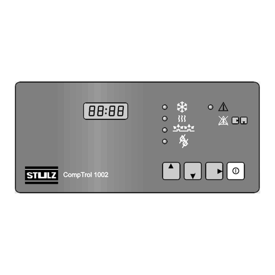
2. Operation and Status Elements Face Plate Status "cooling" Status "reheat" Status "humidification" Status "dehumidification" 4-digit LED-Display Alarm Alarm reset START/ STOP key "Right arrow" key "Down arrow" key "Up arrow" key Rear Plate DIP- switch 1-4 Connection board E/0310/50/5... - Page 6 4-Digit LED-Display In this LED-display all controlling parameters such as setpoints, actual values and limiting values, are shown. Status LED Status LED shows actual operation mode of controller. As a function is switched on, the corres- ponding Status LED is indicated. On a CW-Unit, Status LED "cooling" indicates when CW-valve has an opening degree bigger than 0%.
- Page 7 Consequences of alarm inputs "auxiliary alarm 1" and "auxiliary alarm 2" de- pends on position of DIP-switch 3. DIP-switch 3 can be switched at any time, even during controller operation. The function of this switch is immediately valid without further measures. DIP-Switch Temperatures in °C or °F can be chosen by this DIP-switch.
- Page 8 Operation Mode "Start" Control system and unit are in operation. Unit functions are turned on when start values match setpoints of corresponding functions. Limit values are supervised. Menu item 1 is shown. Display is alternating between actual value "temperature" and actual value "humidity" in 2- second- inter- vals.
-
Page 9: Start-Up
Start- up in Operation Mode "Stop" If the CompTrol 1002 was in operation mode "Stop" before cutting off the power supply, the cont- roller will be in this operation mode again after the restart. Three possibilities of how the unit has... - Page 10 Start/Stop-key. Start- up with new EEPROM If the CompTrol 1002 is started with a new EEPROM, the following symbol appears in the display during the initial phase (about 1 second): The standard values of the program memory EPROM are loaded into the EEPROM and into the RAM.
-
Page 11: Menu
4. Menu Actual values: temperature / humidity Actual opening degree CW-valve (only at CW-version) Temperature setpoint Sequencing for 2 units Humidity setpoint Integral factor Limit value RT too high Unit start delay Limit value RT too low Humidity sensor adjust. Limit value RH too high Temperatur sensor adjustment... - Page 12 Menu item Meaning Display Further Functions Actual value "Temperature" ...1s... alarm reset Actual value "Humidity" Setpoint "Temperature" Setpoint "Humidity" Limit value "Room tempera- ture too high" Limit value "Room tempera- + PASSWORD ture too low" enter mode Limit value "Room humidity too high"...
- Page 13 Menu item Meaning Display Further Functions CW-valve opening degree for dehumidification in % 2. Compressor start value Reheat 1 start value Reheat 1 + 2 hysteresis + PASSWORD Reheat 2 start value enter mode Humidification start value modification of values by Humidification hysteresis leaving the enter mode Dehumidification start value...
- Page 14 Menu item Meaning Display Further Functions + PASSWORD Integral factor enter mode Sequencing for 2 units modification of values by leaving the enter mode with ---------------- Actual opening degree CW-valve The menu items 8a-11a and 25 are valid for CW-units. The menu items 8b-11b are valid for units with a compressor.
- Page 15 Item Actual Values Display is alternating between actual value "temperature" and actual value "humidity" in 2- second- intervals. Humidity is shown in % r.h. Actual value "humidity" is marked by an H. Temperatures are shown in °C (marked by C) or °F (marked by F). This can be chosen by DIP- switch 4 at any time.
- Page 16 Item a. CW-units b. Units with Compressor Valve Modulating Time Compressor Restart Delay Modulating time of CW-valve (operating level In this item the restart delay in seconds is 0% up to operating level 100% in seconds) entered. After a compressor shut down, it will be entered in this menue point.
- Page 17 Item Reheat 1 Start Value Reheat 1 + 2 Hysteresis Reheat 2 Start Value Parameters of reheat's stages 1+2 can be entered in these items The hysteresis is valid for both stages. Humidification Start Value Humidification Hysteresis Parameters of 2-point-humidification can be entered in these items. Dehumidification Start Value CW-units: For dehumidification CW-valve opens to the indicated opening degree entered in item...
- Page 18 Item CPU- Address CPU- Address can be entered in this item. If CompTrol 1002 is connected to a STULZ Monitoring System, an address between 1 and 32 for every connected controller has to be adjusted. Temperature Sensor Adjustment Temperature sensor adjustment can be done in this item. The actual value is indica- ted and can be adjusted to another value, that is measured by use of an independent temperature sensor.
- Page 19 Item Integral Factor for Setpoint “Temperature” In this point of the menue, the I-proportion of the PI controller can be preset. If a non- zero value is entered, the control discrepancy, which is characteristic for P-controllers, is avoided. The setpoint SP entered becomes “control setpoint”.
- Page 20 Item For test purposes or in case the I-proportion is not desired, the integral factor is set to zero. A P-controller exists and the control setpoint is equal to the setpoint. Under the following circumstances, the setpoint is immediately taken over into the control setpoint: - during initialization phase (switch on voltage) - turning on (start mode)
- Page 21 Item If unit 1 is the StBy-unit (i.e. the unit, which is not in operation at the moment, due to the sequencing), a colon („:“) is displayed in item „U“. If unit 2 is the StBy-unit the colon disappears. 3K below the alarm „temperature too high“ the StBy-unit starts in addition. The sequencing time will not be interrupted.
-
Page 22: Alarms And Failures
5. Alarms and Failures General An alarm or failure is indicated via a short text in the display and status-LEDs. Conditions that activate the alarm relay are shown in the following table. The delay with which the alarm relay is activated, depends on the failure and is documented in the table. Texts for alarms and failures are only shown in operation mode "start", in menu item 1 , and in operation mode "stop". - Page 23 If the alarm input is supplied with 24V, there is no failure/alarm. If the alarm inputs are not used they have to be supplied with 24V or, if possible, the hysteresis of the function has to be set to „0“. The inputs concerned are: Heating 1 and 2 Air volume 1 and 2...
- Page 24 Table of Alarms and Failures Alarms Display Meaning Alarm LED Alarm Relay Time Delay Consequences Room temperature too high about 30 s ------------ Room temperature too low about 30 s ------------ Room humidity too high about 30 s ------------ Room humidity too low about 30 s ------------ Failures...
-
Page 25: Control Diagram For Cw-Units
6. Control Diagram for CW-Units Temperatur Control Diagram Setpoint Temperature Temperature too low Reheat 2 Reheat 1 CW-Cooling too high Humidity Control Diagram Setpoint Humidity Humidity too low Humidification Dehumidification too high rel. hum. Numbers refer to the menu items. E/0310/50/25... - Page 26 Control Diagram for Units with Compressor Temperature Control Diagram Setpoint Temperature Temperature too low Reheat 2 Reheat 1 too high 1. Compressor 2. Compressor Humidity Control Diagram Setpoint Humidity Humidity too low Humidification Dehumidification too high rel. hum. Numbers refer to the menu items. E/0310/50/26...
-
Page 27: Specification Comptrol 1002
7. Specification CompTrol 1002 7.1 Technical Data Dimensions L x W x H 280 x 195 x 45 mm (11.0" x 7.7" x 1.8") Power supply (24 V + 20 % / - 15 %) V AC X10, X11.1 grounded... -
Page 28: Connection Diagram Of Processor Board C1002
7.2 Connection Diagram of Processor Board C1002 24 V~ Sensor shut valve / compressor 1 open valve / dehumidification Reheat 1 Reheat 2 / Sequencing out Humidifier Alarm / Sequencing out Sensor input 0-20mA Airflow 1. module Filter Reheat Humidification 20µS/cm Ultrasonic 5 µS/cm* / high pressure comp. - Page 29 In a CW application, the CompTrol 1002 is usually used for a proportional valve with motor drive. The operation of the control is explained in the following drawing (example for a 150- seconds- runtime). Operation level / % When connection V+ is supplied with power, the valve is completely opened within 150 seconds (operation level 0% to operation level 100%).
-
Page 30: Bus Connection
High, terminal 33 Driver module The C1002 controller can be integrated in the Stulz bus. The driver module serves to properly adjust the C1002 as a bus participant in dependence of the position within the bus. For a detailed description of the driver module see next page. - Page 31 Driver module The driver module has the following features: 1. a static bus termination (120 Ohm), which can be activated by a jumper. 2. a circuit to set the bias for the bus. By means of two jumpers either a low bias (bus middle) or a high bias (bus end) can be set.
-
Page 32: Connection Diagram For Sequencing At The Processor-Board
7.4 Connection Diagram for Sequencing at the Processor-Board Unit 1 24 V 0 V ALARM 20 21 30 17 Seq. Unit 2 24 V 0 V Seq. ALARM 30 17 20 21 E/0310/50/32... -
Page 33: Specifications Of The Extension Card 1B
With the extension card 1b, additional inputs and outputs are provided for the CompTrol 1002. The extension card 1b is fixed on the CompTrol 1002 by means of the two distance pieces enclosed. Electric connection to the basic board is made by a 20 pins plug connector. As soon as the extensi- on card has been connected, the alarms aux 2 / fire and smoke detector and Ultrasonic humidifier... -
Page 34: Technical Data Extension Card 1B
8.1 Technical Data Extension Card 1b 125 x 70 x 30 mm (4.9" x 2.8" x 1.2") Dimensions L x W x H (24 + 20 % / - 15 %) V AC Power supply X20.24 grounded Power consumption 0.4 AT Fuse Operating elements 6-fold DIP switches... -
Page 35: Connection Diagram Of The Extension Card 1B
8.2 Connection Diagram of the Extension Card 1b Compressor 2 Sequencing out Sequencing 24 V Damper Sequencing in high pressure comp.2 low pressure comp.2 Airflow module 2 Temperature limit DIP switches Aux2 / Firestat and smoke detector Ultrasonic 5µS/cm X20: connection terminal 18 pins X21: extension plug 20 pins The consumer is connected to 24 V. -
Page 36: Connection Diagram For Sequencing With Extension Card
8.3 Connection Diagram for Sequencing with Extension Card Unit 1 24 V 0 V Extension 1b ALARM 15 11 20 21 Seq. Unit 2 24 V 0 V Seq. Extension 1b ALARM 15 11 20 21 E/0310/50/36... -
Page 37: Appendix
9. Appendix 9.1 Standard Setting Standard Menu item Range value Adjusted value 2. Setpoint temperature 10,0...30,0°C 24,0°C 3. Setpoint humidity 10...90% 4. Limit value temperature too high 10...50°C 35°C 5. Limit value temperature too low 0...30°C 0°C 6. Limit value humidity too high 30...90% 7. -
Page 38: Password
9.2 Password In menu items 2 to 24 a password is requested in enter mode. The display shows To enter the password, keys must be pressed within 5 seconds. Now the display flashes and the parameter can be modified. Should a wrong key be pressed or the time be exceeded, entering of password is aborted. E/0310/50/38...
Need help?
Do you have a question about the CompTrol 1002 and is the answer not in the manual?
Questions and answers
Hi our stulz comptroller 1002 AC is not running showing OFF = sign in display
The CompTrol 1002 AC controller may display an OFF sign and not run because it is in operation mode "Stop." This can happen if the unit was in "Stop" mode before a power cut. The controller returns to the same mode after restart. The unit can be stopped in three ways: by the local Start/Stop key, by remote On/Off, or by software via the monitoring system. If stopped from multiple sources, bars appear in the fourth character position on the display. Restart is only possible using the local Start/Stop key, which has the highest priority.
This answer is automatically generated
Hello, i would like to know how to remove password since i don't remember it. Also how to stop alarm