Advertisement
Quick Links
Necessary Tools:
Fretsaw
Ruler,pencil
Sandpaper
Wood glue
All purpose glue
Drill ø4; 4,5,10 mm
Soldering iron, solder
Wire strippers
Side cutters
File
Scissors
Acrylic paint
2-component glue
or glue gun
E110732#2
110.372
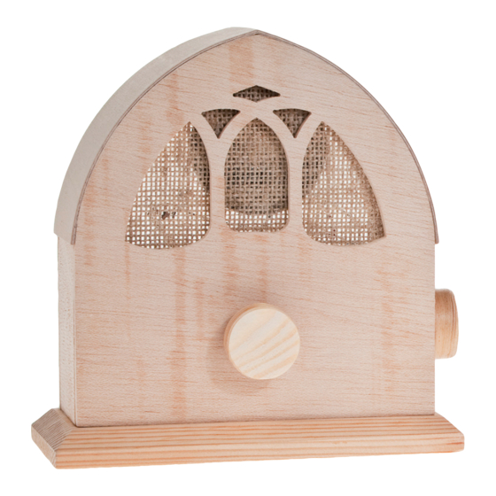
F M R a d i o
The OPITEC range of projects is not intended as play
toys for young children.They are teaching aids for
young people learning the skills of Craft, Design and
Technolo- gy.These projects should only be underta-
ken and tested with the guidance of a fully qualified
adult. The finished projects are not suitable to give to
children under 3 years old. Some parts can be swallo-
Please Note
wed. Dan- ger of suffocation!
1
Advertisement

Subscribe to Our Youtube Channel
Summary of Contents for Opitec 110.372
- Page 1 Ruler,pencil Sandpaper Please Note Wood glue The OPITEC range of projects is not intended as play All purpose glue toys for young children.They are teaching aids for Drill ø4; 4,5,10 mm young people learning the skills of Craft, Design and Soldering iron, solder Technolo- gy.These projects should only be underta-...
-
Page 2: Parts List
INSTRUCTIONS PARTS LIST Code Quantity Size (mm) Description Teile-Nr. PLywood Housing 300x210x5 Wooden strip 200x40x15 Base plate Modelling plywood Top (Version 1) 300x60x1,5 Wooden wheel ø 30 knob Jute material 200x145 Loudspeaker cover Loudspeaker ø57 Loudspeaker cover Plastic tube ø4/3 Insulation IC holder 8leg Cable... - Page 3 INSTRUCTIONS 5. Shorten the end of the potentiome- 2. Cut the jute (5) as shown so that it 3. Use PVA wood glue to ensure that ter (15) with a fine bladed saw to covers the cut out on the front of the the jute lays flat over the shapes 10mm and insert it into the hole in housing.
- Page 4 INSTRUCTIONS 10. Glue the housing centrally on the 11. Cut two 130mm long pieces from 12. Take the wheel (4) and on non pre-glued base the modelling plywood (3) and glue milled side drill a blind hole 6mm them on the housing as shown dia 5mm deep 13.
-
Page 5: Schematic Diagram
INSTRUCTIONS 1MOhm 1,0uF Schematic diagram 4,7 nF 3,3 nF 220 uF TDA 7021T 7052A 470 nF 100 nF 820 pF 4,5 V 3,3 nF Soldering the components on the circuit board: 18. Use a 4mm drill as a former to wind 6 turns of siver wire close together ( See diagram.) Bend the end of the colil as shown Pull the ends of coil carefully apart so that it can be soldered on the circuit board as shown. - Page 6 INSTRUCTIONS - Take the cable from the loudspeakers (each ca. 150mm red + black) stripthe insulation from the ends. Twist the inners to- gether and tin them with solder. The red cable from the plus on the loudspeaker is connected and soldered to the Red L+ on the board.
- Page 7 BAUANLEITUNG Expoded diagram Variantion 1 Exploded diagram Variantion 2 E110732#2...
- Page 8 E110732#1...
- Page 9 INSTRUCTIONS Pattern variation 1 Sale 1:1 Front E110732#2...
- Page 10 INSTRUCTIONS Pattern Variation 2 Scale 1:1 Front Back part Side part Side part E110732#1...
- Page 11 INSTRUCTIONS Pattern Variation 1 Scale 1:1 Back part Side part Side part E110732#2...
- Page 12 INSTRUCTIONS Pattern Variation 2 Scale 1:1 Cover E110732#1...
- Page 13 INSTRUCTIONS Cutting plan Varaition 1+2 Front Cover Side Side part Front E110732#2...
Need help?
Do you have a question about the 110.372 and is the answer not in the manual?
Questions and answers