Advertisement
Quick Links
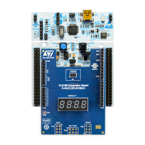
How to use the VL6180 proximity sensor X-NUCLEO-6180A1 expansion board
Introduction
This user manual provides detailed hardware information on the X-NUCLEO-6180A1 expansion board (see figure below). This
board is designed around the VL6180 proximity sensor and it is compatible with the STM32 Nucleo and Arduino Uno boards.
The document provides an introduction to the proximity sensing capabilities of the VL6180 module which is based on ST's
patented Time-of-Flight (ToF) technology. Several ST expansion boards can be superposed through the Arduino connectors,
which allow development of VL6180 applications with Bluetooth or WiFi interfaces.
Order code
X-NUCLEO-6180A1
References
•
VL6180 datasheet: Time-of-Flight proximity sensor and IR emitter two-in-one module
•
X-NUCLEO-6180A1 data brief: Proximity Time-of-Flight sensor expansion board based on VL6180 for STM32 Nucleo
UM2657 - Rev 1 - March 2020
For further information contact your local STMicroelectronics sales office.
Figure 1.
X-NUCLEO-6180A1 expansion board
Table 1.
Ordering information
X-NUCLEO-6180A1 expansion board for use with STM32 Nucleo board
with the STM32 Nucleo board
Description
UM2657
User manual
www.st.com
Advertisement

Related Manuals for ST VL6180


Summary of Contents for ST VL6180
- Page 1 This user manual provides detailed hardware information on the X-NUCLEO-6180A1 expansion board (see figure below). This board is designed around the VL6180 proximity sensor and it is compatible with the STM32 Nucleo and Arduino Uno boards. The document provides an introduction to the proximity sensing capabilities of the VL6180 module which is based on ST's patented Time-of-Flight (ToF) technology.
-
Page 2: Hardware Description
UM2657 Hardware description Hardware description This section describes the X-NUCLEO-6180A1 expansion board features and provides information on the electrical schematics. Figure 2. X-NUCLEO-6180A1 expansion board block diagram UM2657 - Rev 1 page 2/14... -
Page 3: Board Description
• the necessary connectivity for the application It is fundamental to program a microcontroller to control the VL6180 through the I2C bus and drive the 4-digit display on-board. Application software and examples of C-ANSI source code are available on www.st.com/ VL6180. - Page 4 UM2657 Board description Table 2. Arduino left connector on STM32 Nucleo board X-NUCLEO-6180A1 X-NUCLEO-6180A1 expansion board CN number Pin number Pin name MCU pin expansion board function Level shifter reference (3.3 V) Power 3.3 V supply CN6 power — Interrupt signal from X-NUCLEO-6180A1 GPIO1_B INT_B bottom breakout plug-in...
- Page 5 This allows the development of applications that can control up to four VL6180 devices. The I2C bus is shared with the VL6180 on-board I2C bus. The GPIO1 (interrupt) pins and GPIO0 (reset) pins are separate pins to control each sensor separately.
- Page 6 UM2657 Board description Figure 4. Connections of VL6180 breakout boards Note: The VL6180 breakout boards can be ordered under the reference: VL6180-SATEL Figure 5. VL6180 SATEL (2x breakout boards) UM2657 - Rev 1 page 6/14...
-
Page 7: Electrical Schematics And List Of Materials
This regulator is requested to convert the 3.3 V coming from the Nucleo or Arduino boards to 2.8 V. In a final product, the 2.8 V regulator (if it exists) can be used to supply the VL6180. UM2657 - Rev 1... - Page 8 UM2657 Electrical schematics and list of materials Figure 8. X-NUCLEO-6180A1 expansion board with level shifters The level shifters are used only to provide adequate voltage for the I/O’s and I2C bus which allows a 5 V Arduino board to be connected without hardware modifications. In a final product, depending on the power management tree, the level shifters could be omitted.
- Page 9 UM2657 Electrical schematics and list of materials Figure 10. X-NUCLEO-6180A1 expansion board with display control Figure 11. X-NUCLEO-6180A1 expansion board with GPIO expander UM2657 - Rev 1 page 9/14...
- Page 10 C7, C8, C10, C11 100 nF 0603 R17, R18, R19, R20 4.7 kΩ U2, U3 ST2329AQTR QFN10 Level shifter External VL6180 and Nucleo_Arduino connectors 47 kΩ 0603 10 kΩ 0603 Display control R6, R7, R8, R9, R10, R11, R12, R13 300 Ω 0603 R28, R29, R30, R31 100 kΩ...
-
Page 11: Safety Considerations
Failure to prevent electrostatic discharge could damage the device. Laser safety The VL6180 contains a laser emitter and corresponding drive circuitry. The laser output is designed to remain within Class 1 laser safety limits under all reasonably foreseeable conditions, including single faults, in compliance with the IEC 60825-1:2007. -
Page 12: Revision History
UM2657 Revision history Table 6. Document revision history Date Version Changes 10-Mar-2020 Initial release UM2657 - Rev 1 page 12/14... -
Page 13: Table Of Contents
UM2657 Contents Contents Hardware description ............. . 2 Board description . - Page 14 ST’s terms and conditions of sale in place at the time of order acknowledgement. Purchasers are solely responsible for the choice, selection, and use of ST products and ST assumes no liability for application assistance or the design of Purchasers’...
Need help?
Do you have a question about the VL6180 and is the answer not in the manual?
Questions and answers