
Summary of Contents for Hy-Gain DCU-1
- Page 1 Digital Control Unit for HAM-IV and T-2X Model DCU-1/ DCU-1X Instruction Manual 308 Industrial Park Road Starkville, MS 39759 USA PH: 662-323-9538 FAX: 662-323-6551...
-
Page 2: Table Of Contents
TABLE OF CONTENTS Page Chapter 1- Installation and Operation ....................1-1 Section 1. Components of the DCU-1 "Pathfinder" digital Control Unit.......... 1-1 General ............................. 1-1 Section 2. DCU-1 Digital Control Unit Specifications..............1-2 Section 3. Precautions........................1-3 Section 4. Installation......................... 1-4 Section 5. - Page 3 LIST OF ILLUSTRATIONS Page Front View ......................1-2 Back ........................1-2 Control Cable Connector Attachments ..............1-5 DCU-1 Display ...................... 1-7 Wiring Guide ......................1-9 Command ......................1-9 Sample Program....................1-10 Front Panel PCB ....................1-14 Control PCB and External Components ..............1-14...
-
Page 4: Chapter 1 Installation And Operation
CHAPTER 1 INSTALLATION AND OPERATION Section 1. Components of the DCU-1 "Pathfinder" Digital Control Unit General Description Your existing rotator unit (HAM IV, T2X, or The DCU-1 "Pathfinder" digital control unit fea- compatible) must be connected to the control tures 6 memory presets, automatic brake delay unit with an 8-wire cable. -
Page 5: Section 2. Dcu-1 Digital Control Unit Specifications
Section 2. DCU-1 Digital Control Unit DCU-1 Digital Control Unit Specifications: Size 8.5"x4.3"x9.0" (W x H x D) (21.6 x 11.0 x 22.8 cm) Control Unit Display: Type Gas Plasma, Amber filter Scale 5 degree (Analog), 1 degree (Digital) Blanking... -
Page 6: Section 3. Precautions
If this equipment does cause harmful interference to radio or television The DCU-1 Control Unit is not weatherproof and reception, which can be determined by turning the must be located in a house or other protected equipment off and on, the user is encouraged to location. -
Page 7: Section 4. Installation
Older HAM-M, II, III or IV and older T2X units may be sluggish at temperatures less than 0 degrees F. The DCU-1 checks for rotator movement upon pressing "START", and if no movement is detected within 8 seconds, it will stop trying to... -
Page 8: Section 5. Wiring And Check Out
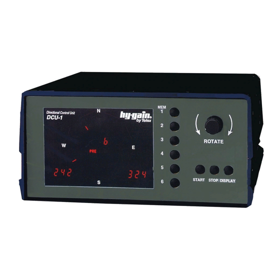
Section 5. Wiring and Check-Out Wiring and Check-Out 3. If this is a new installation, assemble the l. Write down the colors of the wires attached to rotator cable as shown in Figure 3, or your existing rotator control unit: purchase a pre-assembled cable. - Page 9 Belden 8448 Belden 9405 IEWC #8612 Table 2 5. The DCU-1 display should look similar to the 6. If the current bearing display shows a number display shown in Figure 4. The numeric between "000" and "359", then proceed. Twist...
-
Page 10: Dcu-1 Display
DCU-1. power is disconnected for a long period of time. You may use previously stored memory presets The center of rotation can be selected as any and the knob to select new bearings. -
Page 11: Section 6. Operation Of Dcu-1 Control Unit
Section 6. Operation of DCU-1 Control Operation of DCU-1 Control Unit Precautions: Normal Operation 1. Thermal Protection: If the rotator fails to turn The numeric display in the lower left corner and after 4 or 5 minutes of continuous operation, the outer circle tick mark always indicates the the thermal switch has come into play. -
Page 12: Computer Operation
The cable which is attached to the computer and The DCU-1 may be controlled from your to the DCU-1 should have a DB9 male connector computer via a RS-232 cable connection. The at one end and either a DB9 female or DB25 rear panel has two (2) RS-232 connectors. - Page 13 A sample BASIC program is shown in Figure 7 After a command is sent to the DCU-1, all other motor and brake operation is automatic. There which can be used to control operation of the are no provisions at this time to send current DCU-1.
-
Page 14: Section 7. Troubleshooting
ONLY with Hy-Gain HAM-IV (type) connector wiring carefully between the rotator and T2X rotator systems. Do not try to use this and the DCU-1 control box. Pin #1 must attach to control on other systems! Pin #1, etc... Incorrect wiring will burn out the rotator potentiometer and void the warranty. -
Page 15: Ground Wires
Unintentional grounds on cable leads can burn See Table 2. For cable runs over 300 feet, you out the line fuse in the DCU-1 control box or may wish to move the motor capacitor to the burn out the potentiometer in the rotator. If pin tower. -
Page 16: Checking The Control Unit Voltages
To check the control unit voltages, first remove You have 8 seconds after pressing "START" to the rotator control cable from the DCU-1 control make each measurement. The DCU-1 checks for box, then plug the line cord into a 110 VAC... -
Page 17: Section 8. Dcu-1 Control Unit Block Diagrams
Section 8. DCU-1 Control Unit Block Diagrams Figure 8 Front Panel PCB Figure 9 Control PCB and External Components... - Page 18 Section 9. DCU-1 Control Unit Replacement Parts Part Description Qty 870804 DCU-1 Assembly, 120 V................1 870842 DCU-1 Assembly, 220 V................1 1034403 Fuse 3 Amp 3 AG (120 VAC) ..............1 (710053) Fuse i AMP 5 x 20 mm (220 VAC) ............1 1056300 Fuse Holder (120 VAC)................1...
- Page 19 DCU-1 Control Unit Replacement Parts List (continued) Part Description 870806 Transformer Assembly, (120 VAC)............1 1073501 Transformer Assembly, (220 VAC)...........….....1 870807 PCB Assembly, front panel............…....1 870808 PCB Assembly, control.……..............1 8800102114 Connector D, 9 pin, male (Part of 870848 Wire Assembly) ...... 1 8800102132 Connector D, 9 pin, female (Part of 870848 Wire Assembly) ....
- Page 20 Hy-Gain Warrants to the original owner of this product, if manufactured by Hy-Gain and purchased from an authorized dealer or directly from Hy-Gain to be free from defects in material and workmanship for a period of 12 months for rotator products and 24 months for antenna products from date of purchase provided the following terms of this warranty are satisfied.
Need help?
Do you have a question about the DCU-1 and is the answer not in the manual?
Questions and answers