Table of Contents
Advertisement
Quick Links
Advertisement
Table of Contents

Summary of Contents for FlowMotion 2001V Series
- Page 1 2001V Series Peristaltic Chemical Feed Pump...
- Page 3 Installation and Operation Manual 2001V Peristaltic Chemical Feed Pump July 2020 Flomotion Systems, Inc. 3 N. Main St, Middleport, NY 14105 Toll Free: (800)909-3569 (U.S. & Canada) Tel: (716)691-3941 Fax: (716)691-1253 info@flomotionsystems.com www.flomotionsystems.com...
-
Page 4: Table Of Contents
1.3 R ......................................6 ECEIVING 1.4 C ...................................6 USTOMER ODIFICATION 1.5 I ..............................6 NFORMATION FOR ETURNING UMPS 2.0 – 2001V Series Pump and Pumphead..........................7 2.1 T ............................8 UBING PINDLE AND OVER NSTALLATION 2.2 M .........................9 OUNTING UMP ON EARBOX NSTALLATION OF OLLET 2.3 P... -
Page 5: System Overview
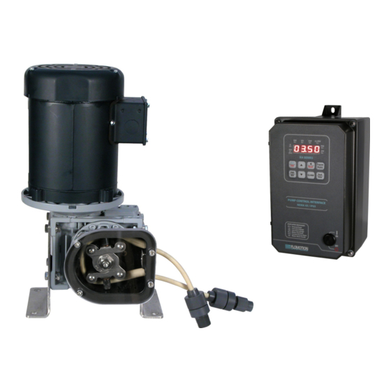
1.0 - System Overview The 2001V Chemical Feed Pump consists of a controller, motor, gearbox and peristaltic pump. 1.1 Safety In the interests of safety, this pump and the tubing selected should only be used by competent, suitably trained personnel after they have read and understood this manual, and considered any hazard involved. Any person who is involved in the installation or maintenance of this equipment should be fully competent to carry out the work. -
Page 6: 2001V Series Pump And Pumphead
ROLLER ASSEMBLY COLLET SCREW 4MM HEX WRENCH 7 NT.M 60 IN.OZ IMPORTANT: The 2001V Series is equipped with a pump cover for safety and protection against chemical spills. The cover must be installed whenever the pump is in use. -
Page 7: Tubing, Spindle And Cover Installation
2.1 Tubing, Spindle and Cover Installation ! IMPORTANT: Disconnect pump controller from power supply BEFORE changing tubing! Item No. Part No. Description Pump Collet & Hose Assy. 100329 Roller Assembly 100330 Cover 100324 Collet Screw 100305C Cover Gasket 100307C Cover Screw Tube Varies with tubing selection* Tube Seal... -
Page 8: Mounting Pump On Gearbox, Installation Of Collet
2.2 Mounting Pump on Gearbox, Installation of Collet Item No. Part No. Description Pump Housing with Tube Seal 100306 Collet 100330 Pump Mounting Screws Tubing... -
Page 9: Pump Mounting And Collet Installation Procedure
2.3 Pump Mounting and Collet Installation Procedure 1. To install the pump housing on the gearbox, slide it over the central pilot on the gearbox adaptor plate. Next install and torque the mounting screws to 5 NT.M (45 in. oz). 2. - Page 10 3. Remove 5mm collet screw. 4. Remove the roller assembly. 5. Remove worn pump tubing from pumphead.
- Page 11 6. Remove and inspect collet for wear. Note that the collet may remain in the roller assembly when the roller assembly is removed from the pump shaft. 7. Clean inside of pump housing with damp rag or an appropriate cleaning solution to remove any chemical or tubing residue.
- Page 12 2. Mark an 11” section of hose, which will be the portion, contained within the pump. Leave sufficient excess on the suction and discharge sides of the pump for the desired connections. If you leave the excess intake tubing in a coil near the pump it will make it easy to feed a new section of tubing through the rollers when the section in the pump becomes worn.
- Page 13 4. Loop tubing around roller assembly between guides as shown. Remove slack in tubing while rotating roller assembly and sliding onto collet. Mark an 11 inch 5. Align marks on tubing with outside edge of the tubing length of tubing clamp.
- Page 14 7. Tighten tube seal clamp screw. Be sure to tighten firmly to prevent “tubing walk.” Tubing walk can occur when the tube seal is the wrong size or is not sufficiently tight to keep the rollers from pulling the tubing through the pump as it rotates.
-
Page 15: Tubing & Connections
2.5 Tubing & Connections Tubing adapters are available for many configurations. See the drawing below for details. 2001V SERIES ESTIMATED PUMPING CAPACITY* *Actual flow rates may vary #119 #120 Tubing No. 1.6mm bore 3.2mm bore 4.8mm bore 6.4mm bore 8mm bore 9.6mm bore... -
Page 16: 2001V Series Gearbox
3.0 – 2001V Series Gearbox 3.1 Run-in Period The maximum efficiency of worm reducers is obtained after a “Run-In” period. The length of time required will depend on the load applied and may be two to four hours at rated load and will be considerably longer at lighter loads. -
Page 17: Operation And Wiring
4.0 – K4 Pump Controller 4.1 Operation and Wiring For complete details about the motor drive controller please refer to the included K4 SERIES Operating Instructions booklet. IMPORTANT: Make sure the Mains voltage jumper is in the correct location for the supplied voltage. - Page 18 4.4 Setting the maximum pumping rate. 1. Fill a calibration cylinder (best to use water, not chemical for testing and calibration) 2. Run the pump at full speed and time the drawdown for 30 sec. (from the zero level in the cylinder) 3.
- Page 19 4.5 Controller Wiring Examples...
-
Page 20: 2001 Series Tubing Rupture Detector
5.0 - 2001 Series Tubing Rupture Detector Rupture Detector System Overview 5.1 Alarm Causes A rupture alarm is triggered by the presence of a conductive fluid in the pump. When the fluid bridges the two stainless steel electrodes in the LIQUID SENSOR in the pump the alarm is triggered. 5.2 What to do in an alarm condition To clear the alarm, first stop the pump and disconnect power from the pump controller. - Page 21 Warranty Flomotion Systems, Inc. warrants the 2001 Series pumps to be free of defects in material and workmanship for a period of eighteen months from the date of sale to the user, or two years from the date of shipment, which ever occurs first.
Need help?
Do you have a question about the 2001V Series and is the answer not in the manual?
Questions and answers