Table of Contents
Advertisement
Quick Links
Advertisement
Table of Contents

Summary of Contents for Control Applications ElNet VIP
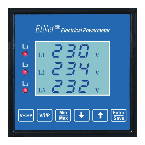
- Page 1 ElNet VIP Current & Power Multimeter Rev 1.7...
-
Page 2: Table Of Contents
Table of Contents 1. Mechanical Installation ............. 3 2. Wiring diagram ..............4 3. Specifications ..............5 1.3 Technical Specifications ..........5 3.2 Measuring Specifications ........... 5 4. Current transformer ratio settings ........6 5. -
Page 3: Mechanical Installation
Dear customer, thank you for selecting the VIP Multimeter for measurements of voltage, current, power and power factor. 1. Mechanical Installation Comment: Please do not install the VIP Multimeter close to electrical bars. Please leave enough space for approaching the device from its back side for providing technical support. -
Page 4: Wiring Diagram
2. Wiring diagram... -
Page 5: Specifications
3. Specifications Technical Specifications Item Description Power requirements 110 or 220 VAC ± 10%, 60/50 Hz, 20VA Dimensions (HxWxD) 96x96x80 mm Shipping Weight 514 gr. Voltage limits 1000VAC Current limits Enclosure material ABS + Antiflame Operating temperature -20 - + 70 C Storage temperature -20 - + 80 C Humidity... -
Page 6: Current Transformer Ratio Settings
4. Current transformer ratio settings 4.1 Press the "Enter" button for about 6 seconds. 4.2 The enter password screen will appear: "COD". 4.3 Use ↑ ↓ button to change the code to "1" and press Enter. 4.4 The current transformer set screen will appear, on the second line the secondary value of current transformer (5A). -
Page 7: Electrical Values Display
6. Electrical values display 6.1 Click on the “V/I/P” button, each additional click will zoom to the next measured item or use the "↑ ↓" buttons (each click scrolls the screens circularly), it is possible to browse among all the display screens including three-phase display of voltage, current, power, frequency, power factor. -
Page 8: Minimum \ Maximum Values Display
8. Minimum \ Maximum values display 8.1 Clicking on the “Min/Max” button will zoom to the next Min\Max item or use the "↑ ↓" buttons (each click scrolls the screens circularly). The first screens present the highest measured values of voltage and current (Hi); the next screens present the lowest measured values of voltage and current (Lo) and then respectively high and low frequency and power factor for each phase. -
Page 9: 10. No Volt Relay
10. No volt relay 10.1 General: When the voltage is proper (above 50VAC, adjustable) and the phases' order is proper the indication relay is closed, as appears at the wiring diagram. The maximum current that is possible to transfer through this relay is 150ma which is enough to operate a regular control relay.
Need help?
Do you have a question about the ElNet VIP and is the answer not in the manual?
Questions and answers