
Summary of Contents for Matrix Electrónica MTX Terminals MTX-GTW
- Page 1 MTX‐GATEWAY MTX‐GATEWAY Hardware User Guide www.mtxm2m.com www.matrix.es 2015/12 v1.8 Page 1 55 MTX Terminals® by MATRIX ELECTRONICA S.L.U ...
-
Page 2: Important Information
MTX‐GATEWAY General Notes Product is deemed accepted by recipient and is provided without interface to recipient’s products. The documentation and/or product are provided for testing, evaluation, integration and information purposes. The documentation and/or product are provided on an “as is” basis only and may contain deficiencies or inadequacies. The documentation and/or product are provided without warranty of any kind, express or implied. To the maximum extent permitted by applicable law, Matrix Electronica ... -
Page 3: Revision Information
MTX‐GATEWAY Revision information Revision Date Author Changes 1.0 2013/07 RR First draft 1.1 2013/11 RR General update 1.2 2014/05 RR HW V1.02 update 1.3 2014/10 AEM/TP Language style revision 1.4 2014/11 AEM Added mechanical drawings 1.5 2014/12 AEM Minor revision 1.6 2015/05 AEM Minor revision 1.7 2015/08 AEM Conformity assessment added 1.8 2015/12 ... -
Page 4: Table Of Contents
MTX‐GATEWAY Index General Notes ............................ 1 Important information .......................... 2 Service and Support .......................... 2 Revision information .......................... 3 1. Description ............................ 7 1.1 Product label ........................... 7 2. Warranty ............................ 8 3. References ............................ 8 4. Technical Data .......................... 9 4.1 System architecture and system functionality ................ 9 4.1.1 Block diagram ........................ 9 4.1.2 Technical data electronics .................... 9 4.1.2.1 External interfaces ...................... 10 4.1.2.2 Internal interfaces ...................... 10 4.1.2.3 User’s interfaces ...................... 10 4.1.2.4 System components ...................... 10 4.1.3 ... - Page 5 MTX‐GATEWAY 5.2.3 Wifi .......................... 22 5.2.4 RF Card .......................... 23 5.2.4.1 Wavecard ........................ 23 5.2.4.2 MOD‐RF ......................... 24 5.2.5 Extension Header ...................... 24 5.3 User Interfaces ........................ 24 5.3.1 Status LED ........................ 24 5.3.2 DIP Switches ........................ 25 5.4 System Components ...................... 26 5.4.1 Temperature Sensor ...................... 26 5.4.2 EEPROM ......................... 26 5.4.3 RTC .......................... 26 6. Mechanics Specification ........................ 27 6.1 ...
- Page 6 MTX‐GATEWAY 9. Declaración de conformidad (Spanish) .................. 43 9.1 Estándares de homologación europea .................. 43 9.2 Aprobación PTCRB ......................... 45 9.3 Conformidad FCC ........................ 46 9.3.1 Tasa de absorción específica (SAR) ................ 46 9.4 Certificación AT&T ......................... 47 10. Regulatory and type approval information ................ 48 10.1 Directives and standards ....................... 48 10.2 SAR requirements specific to portable mobiles .............. 51 10.3 SELV requirements ........................ 52 11. RoHS Statement ........................ 53 12. Disposal of old electrical & electronic equipment .............. 53 13. Sales contact .......................... 54 ...
-
Page 7: Description
MTX‐GATEWAY 1. Description The MTX‐GATEWAY is designed to be driven by the TQMa28 module and offers PC core functionalities and standard interfaces. This user guide provides information about the components, features, connectors and signals available on the MTX‐GATEWAY. 1.1 Product label The label fixed to the bottom of a MTX devicel comprises the following information: No. Information 1 MTX M2M logo 2 Product name (model) 3 Product ordering number 4 Hardware and Firmware Revisions 5 MAC address 6 Year/Week of fabrication 7 Barcode (Code 128) (IMEI) 8 Product IMEI 9 ... -
Page 8: Warranty
MTX‐GATEWAY 2. Warranty The information contained within this user guide, including but not limited to any product specification, is subject to change without notice. Matrix Electronica provides no warranty with regard to this user guide or any other information contained herein, and hereby expressly disclaims any implied warranties of merchantability or fitness for any particular purpose with regard to any of the foregoing. Matrix Electronica assumes no liability for any damages incurred directly or indirectly from any technical or typographical errors or omissions contained herein or for discrepancies between the product and the user guide. In no event shall Matrix Electronica be liable for any incidental, consequential, special, or exemplary damages, whether based on tort, contract or otherwise, arising ... -
Page 9: Technical Data
MTX‐GATEWAY 4. Technical Data 4.1 System architecture and system functionality 4.1.1 Block diagram Ethern RS232/485/4 RS23 RS23 Ethernet RS232/485/ RS232 RS232 Transceiver 422 Transceiver Transceiver ADV7125 TQMa28 CAN 1‐Wire WIFI miniP Transceiver DS2482‐100 1‐ RELA RELA Illustration 1: MTX‐GATEWAY block diagram 4.1.2 Technical data electronics The interfaces and system components listed in the following are implemented on the MTX‐GATEWAY. Due to the fact that the board can be installed in a casing, the interfaces are divided into external and internal interfaces. ... -
Page 10: External Interfaces
MTX‐GATEWAY 4.1.2.1 External interfaces 1x VGA 1x USB OTG 2.0 1x Ethernet 1x RS232/485/422 2x RS232 1x CAN 1x 1‐Wire Up to 2 x Relay 1x Power Supply 4.1.2.2 Internal interfaces 1x TQMa28 1x miniPCIe Card 1x WiFi b/g/n 1x RF Card 1x Header for specific extension 4.1.2.3 User’s interfaces 6x Status LEDs ... - Page 11 MTX‐GATEWAY 5. Electronics Specification 5.1 External interfaces Illustration 2: MTX‐GATEWAY PCB top view 5.1.1 Function specification 5.1.1.1 VGA The LCD interface of the TQMa28 drives the Analog Devices ADV7125 to offer a VGA output on the MTX‐GATEWAY. Type of media: VGA Interface on module: RGB, 18bit Signal Characteristic: Compatible with RS‐343A and RS‐170 www.mtxm2m.com www.matrix.es 2015/12 v1.8 Page 11 55 MTX Terminals® by MATRIX ELECTRONICA S.L.U ...
- Page 12 MTX‐GATEWAY 5.1.1.2 USB OTG The USB OTG interface of the TQMa28 (USB0) is offered as a Mini USB B‐Type, Micro USB AB‐type or USB A‐type (mounting option) Micr Type of media: USB OTG 2.0 Hi‐Speed, 5V bus voltage (limited to 500mA) Interface on module: USB OTG Signal characteristic: Compatible with the Universal Serial Bus Specification REV. 2.0 ESD protection: ±15kV human body model Manufacturer Description OUPIIN: 8968‐A04C00SWA Top entry USB A (Default) OUPIIN: 8969‐B05C00SBA Top entry Mini USB B MOLEX: 47590‐0001 Right angle Micro USB AB OUPIIN: 8968‐A04C00RWA Right angle USB A 5.1.1.3 Ethernet The MTX‐GATEWAY directly drives the Ethernet 1 interface. The SMSC LAN8720Ai is used as a PHY. RJ45 (U 1 Type of media: 10/100 Mbit Signal characteristic: Compatible with the IEEE‐802.3 standard ...
- Page 13 MTX‐GATEWAY 5.1.1.4 RS232/485/422 The AUART0 of the TQMa28 drives the RS232/485/422 interface on the MTX‐GATEWAY. The Maxim MAX3160 is used as a transceiver. Plug In addition, two signals are used in order to configure the Maxim transceiver in one of its operational modes: Signal Description SW2_1 RS485/RS232# SW2_2 Half_Duplex/Full_Duplex# Transfer rate: Up to 10Mbit/s (full‐duplex) Interface on module: AUART0 Handshake: RTS# used for clearing the transmission direction ESD protection: ±15kV human body model The following tables show the configuration of the DB15 and Pluggable Terminals of the RS232/485/422 interface (DTE interface). ...
- Page 14 MTX‐GATEWAY 5.1.1.5 RS232 1 The AUART3 interface of the TQMA28 drives the RS232 interface of the MTX‐GATEWAY by default. The Maxim MAX3221EEAE is used as a driver. 3221 (Uu1 Plug Transfer rate: Up to 250Kbit/s Interface on module: AUART3 Handshake: None ESD protection: ±15kV human body model The following tables show the configuration of the DB15 and Pluggable Terminals of the RS232_1 interface. DB15 Connector pinout (J6/J16): Pin Signal ...
- Page 15 MTX‐GATEWAY 5.1.1.6 RS232 2 The AUART1 interface of the TQMA28 drives the RS232 interface of the MTX‐GATEWAY by default. The Maxim MAX3221EEAE is used as a driver. Transfer rate: Up to 250Kbit/s Interface on module: AUART1 Handshake: None ESD protection: ±15kV human body model The following tables show the configuration of the DB15 and Pluggable Terminals of the RS232_2 interface. DB15 Connector pinout (J6/J16): Pin Signal Type Remark 4 ...
- Page 16 MTX‐GATEWAY 5.1.1.7 CAN The CAN 0 port of the TQMA28 directly drives the interface on the MTX‐GATEWAY. The NXP TJA1051T/3 is used as a CAN transceiver. TJA1 (U3) Plug Transfer rate: Up to 1Mbit/s Interface on module: CAN_0 Signal characteristic: Compatible with the ISO‐11898 standard (CAN 2.0B) ESD protection: ±8kV human body model The following tables show the configuration of the DB15 and Pluggable Terminals of the CAN interface. DB15 Connector pinout (J6/J16): Pin ...
-
Page 17: 1-Wire
MTX‐GATEWAY 5.1.1.8 1‐Wire A 1‐Wire interface is available on the MTX‐GATEWAY via the Maxim DS2482‐100 I2C chip. DS24 82‐ Plug (U2) gabl Transfer rate: Up to 400kHz Interface on module: I2C1 Signal characteristic: Standard and Overdrive 1‐Wire communication The following tables show the configuration of the DB15 and Pluggable Terminals of the 1‐Wire interface. ... - Page 18 MTX‐GATEWAY I2C Bus Position Device Address 1 MTX‐GATEWAY 1‐Wire DS2482 0x18 www.mtxm2m.com www.matrix.es 2015/12 v1.8 Page 18 55 MTX Terminals® by MATRIX ELECTRONICA S.L.U ...
-
Page 19: Relays
MTX‐GATEWAY 5.1.1.9 Relays There are four different relay configurations supported by the MTX‐GATEWAY. The device must be ordered with its required corresponding relay. 2 Option A Up Option B Up Option C 1x Option D In order to control the chosen relay, the following TQMa28 GPIOs are available: GPIO TQMa28 internal GPIO reference GPIO_3 gpio0_7 GPIO_4 gpio0_16 Option A: The GPIO_3 drives the SET coil of the Latching Relay meanwhile the GPIO_4 drives the Reset coil. The placement for this option is showed on the following picture (J10). Pin Signal Type Remark 1 RL_COM O Common 2 RL_NC O Normally‐Closed 3 ... - Page 20 MTX‐GATEWAY Option B, C and D: Each GPIO drives one different Relay. The placement for this option is showed on the following picture (J17 and J18) Pin Signal Type Remark 1 NA O Normally‐Open 2 COM O Common 3 NC O Normally‐Closed www.mtxm2m.com www.matrix.es 2015/12 v1.8 Page 20 55 MTX Terminals® by MATRIX ELECTRONICA S.L.U ...
-
Page 21: Power Supply
MTX‐GATEWAY 5.1.1.10 Power Supply For protective and EMC reasons the supply input of the MTX‐GATEWAY is designed very robustly. Plug Fuse AC‐DC Vout Connect 0,5A Out:15 15VDC Switchi Option A: Line Filter Switchi Option B: ng Common Plug Revers Connec e Configuration Option A: Parameter Min. Typ. Max. Unit AC Input Voltage 90 240 264 V DC Input Voltage 120 ... -
Page 22: Internal Interfaces
MTX‐GATEWAY 5.2 Internal Interfaces 5.2.1 TQMa28 The core of the MTX‐GATEWAY is the TQ Components TQMa28 module. The following table shows the key features of this module. Feature Description Processor Freescale iMX287 @ 454MHz RAM 128MB DDR2 FLASH 4GB eMMC EEPROM 32Kb Detailed information about this module can be found on the following link: http://www.tq‐group.com/en/products/industry‐pcs/prod/embedded‐modul‐ tqma28/extb/Main/productdetail/ 5.2.2 miniPCIe Card A miniPCIe Card slot (also known as Mini PCI Express, Mini PCIe and Mini PCI‐E) is available on the MTX‐ GATEWAY. The following table shows the buses supported by the device: Bus Remark USB USB 2.0 SIM UIM signals for GSM and WCDMA applications Diagnostics LEDs LED_WWAN# Control signals PERST#, WDISABLE# One of the following miniPCIe Cards, already tested by Matrix Electronica, can be included on the MTX‐ GATEWAY: Name Description ... - Page 23 MTX‐GATEWAY 5.2.4 RF Card An RF Card connector is available on the MTX‐GATEWAY. Two complete UART interfaces (RX,TX,CTS,RTS), I2C, and 3 GPIOs are available on this connector. The following table shows the connector pinout (MOD1). Pin Signal Type Remark 1 UART4_RX I UART4 Receive Data ...
- Page 24 MTX‐GATEWAY 500mW: Up to 4km Dimensions 25mW: 30x28x7 mm 500mW: 37x30x7 mm Detailed information about this module can be found on the following link: http://www.coronis.com/en/wavecard.html 5.2.4.2 MOD‐RF The MOD1 connector also supports the connection of the Matrix Electronica MOD‐RF module. The following table shows the key features of this module. Feature Description RF Technology Bluetooth 2.1 (Bluegiga WT12) Bluetooth 4.0 (Bluegiga BLE112) Xbee Form Factor compatible RF 2,4GHz (Amber 8426: 868/WMBUS) 5.2.5 Extension Header T.B.D. 5.3 User Interfaces 5.3.1 Status LED The MTX‐GATEWAY has six LEDs to inform the user about different status conditions. The following table shows the different LED indications. Led Status remark DL1 Connected to miniPCIe Card WWLAN# signal. DLp1 On when 5VCC is good DL4 On when 3,3VCC is good www.mtxm2m.com ...
- Page 25 MTX‐GATEWAY DL2 Ethernet link activity LED indication DL3 Ethernet link speed LED indication (On with 100Mbps, OFF with 10Mbps) DLp2 Free for User information. Connected to gpio3_6 5.3.2 DIP Switches The MTX‐GATEWAY has two Dip‐Switches for configuration purposes. The following tables show information about the signals connected to each Dip Switch. SW1: Pin Signal Remark 8 LCD_D04 7 LCD_D03 Booting Configuration Signals. 6 LCD_D02 Check TQMa28 User Guide for more information. 5 LCD_D01 4 ...
- Page 26 MTX‐GATEWAY 5.4 System Components 5.4.1 Temperature Sensor There is a National Semiconductor LM73 temperature sensor on the TQMa28 module. It can be read out via the I2C bus 1. The base address can be taken from the following table. I2C Bus Position Device Address 1 TQMa28 Temperature sensor ‐ LM73 0x49 5.4.2 EEPROM A 64Kibit EEPROM (ST Microelectronics M24C64‐WDW6TP) is on the TQMa28 module. The EEPROM is controlled via the processor’s I2C bus 1. Writing protection (WP) of the EEPROM is not available. The base address can be taken from the following table. I2C Bus Position Device Address 1 TQMa28 EEPROM – M24C46 0x50 5.4.3 RTC A DS1339U RTC module is on the MTX‐GATEWAY board. The RTC is supplied by a super capacitor in order to maintain the information should the main supply be removed. I2C Bus Position Device Address 1 MTX‐GATEWAY ...
- Page 27 MTX‐GATEWAY 6. Mechanics Specification 6.1 Construction PCB outlines including mounting holes 6.1.1 PCB outlines MTX‐GATEWAY 111 mm 188 mm 6.1.2 MTX‐GATEWAY PCB top view www.mtxm2m.com www.matrix.es 2015/12 v1.8 Page 27 55 MTX Terminals® by MATRIX ELECTRONICA S.L.U ...
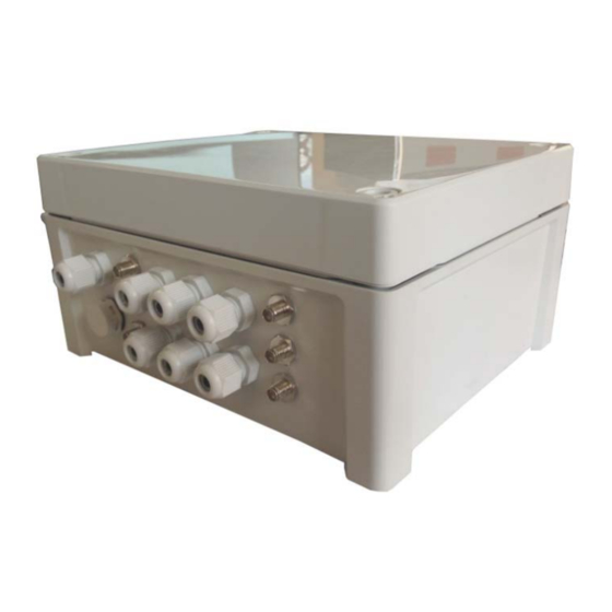
- Page 28 MTX‐GATEWAY 6.1.3 MTX‐GATEWAY enclosure drawings www.mtxm2m.com www.matrix.es 2015/12 v1.8 Page 28 55 MTX Terminals® by MATRIX ELECTRONICA S.L.U ...
- Page 29 MTX‐GATEWAY www.mtxm2m.com www.matrix.es 2015/12 v1.8 Page 29 55 MTX Terminals® by MATRIX ELECTRONICA S.L.U ...
- Page 30 MTX‐GATEWAY MTX‐GATEWAY‐4G‐GPS 2 SMA F antennas: main + diversity 1 SMA F connector 1 SMA RP (Reverse polarity) WiFi connector www.mtxm2m.com www.matrix.es 2015/12 v1.8 Page 30 55 MTX Terminals® by MATRIX ELECTRONICA S.L.U ...
- Page 31 MTX‐GATEWAY 6.1.4 MTX‐GATEWAY‐LC enclosure drawings www.mtxm2m.com www.matrix.es 2015/12 v1.8 Page 31 55 MTX Terminals® by MATRIX ELECTRONICA S.L.U ...
- Page 32 MTX‐GATEWAY www.mtxm2m.com www.matrix.es 2015/12 v1.8 Page 32 55 MTX Terminals® by MATRIX ELECTRONICA S.L.U ...
- Page 33 MTX‐GATEWAY 6.2 Requirements for the superior system The MTX‐GATEWAY has an IP65 enclosure which protects itself again dust, external impact and contact. However, as the MTX‐GATEWAY PCB can be bought as a standalone product, the following points must be considered: 6.2.1 Protection against external effects The MTX‐GATEWAY PCB is not protected against dust, external impact and contact (IP00). An adequate protection has to be guaranteed by the surrounding system. 6.2.2 Thermal management The main heat source is the TQMa28 (in case of the use of a miniPCIe Card, this also has to be taken into account). Information on the cooling of the TQMa28 is to be taken from its specification. www.mtxm2m.com www.matrix.es 2015/12 v1.8 Page 33 55 MTX Terminals® by MATRIX ELECTRONICA S.L.U ...
- Page 34 MTX‐GATEWAY 7. Safety Requirements and protective Regulations Please read the information in this section before starting your integration work! 7.1 Safety instructions PLEASE READ THESE SAFETY INSTRUCTIONS AND KEEP A COPY OF THEM • Always ensure that use of the modem is permitted. The modem may present a hazard if used in proximity to personal electronic medical devices. As a rule, the modem must not be used in hospitals, airports or planes. • Never use the device at a gas station, refuelling point, blasting area or in any other environment where explosives may be present. • Operating the device close to other electronic devices, such as antennas, television sets, and radios may cause electromagnetic interference. • This product is intended to be used with the antenna or other radiating element at least 20cm away from any part of the human body. In applications where this rule cannot be applied, the application ...
- Page 35 MTX‐GATEWAY • The MTX‐GTW Terminal must not be installed nor located in areas where the surface temperature of the plastic case could exceed 85°C. In order to provide strain relief and to avoid transmitting excessive vibration to the device during installation, all cables connected to the MTX‐GTW Terminal must be secured or clamped immediately adjacent to the device's connectors. • To protect the power supply cables, and in order to comply with the fire safety requirements, when the unit is powered from a battery or a high current supply, a fast 1.25A fuse should be connected in line with the positive supply. ...
- Page 36 MTX‐GATEWAY • Never connect more than one modem to a single antenna. The modem can be damaged by radio frequency energy from the transmitter of another modem. • Like any mobile station, the antenna of the modem emits radio frequency energy. To avoid EMI (electromagnetic interference), you must determine whether the application itself, or equipment in the application’s proximity, needs further protection against radio emission and the disturbances it might cause. Protection is secured either by shielding the surrounding electronics or by moving the antenna away from the electronics and the external signal cable. • The modem and antenna may be damaged if either come into contact with ground potentials other than the one in your application. Beware: ground potentials are not always what they appear to be. 7.5 Radio Frequency (RF) exposure and SAR Your wireless modem device is a low‐power radio transmitter and receiver (transceiver). When it is ...
- Page 37 MTX‐GATEWAY Users of the MTX‐GTW wireless modem device are responsible for ensuring that they meet the SAR regulatory requirements of the countries in which they intend to operate the device and that their documentation contains the relevant SAR declaration, certification information and user guidance as appropriate. 7.6 Personal medical devices Wireless modem devices may affect the operation of cardiac pacemakers, hearing aids and certain other implanted equipment. If a minimum distance of 15 cm (6 inches) is maintained between the MTX‐GTW modem radiating antenna and a pacemaker, the risk of interference is limited. If the user’s application is likely to be situated in the vicinity of personnel, a suitable warning should be contained in the equipment manual to this effect www.mtxm2m.com www.matrix.es 2015/12 v1.8 Page 37 55 MTX Terminals® by MATRIX ELECTRONICA S.L.U ...
- Page 38 MTX‐GATEWAY 8. Conformity assessment MATRIX ELECTRONICA S.L.U. C/ Alejandro Sanchez 109 28019 Madrid Spain 8.1 Standards of European Type Approval We declare under our sole responsibility that the products MTX‐GATEWAY‐3G containing Cellular Engine Cinterion engine EHS6 (Type L30960‐N2950‐A100), to which this declaration relates, are labeled with the CE conformity mark. DIRECTIVE 2004/108/EC OF THE EUROPEAN PARLIAMENT AND OF THE COUNCIL of 15 December 2004 on the approximation of the laws of the Member States relating to electromagnetic compatibility and repealing Directive 89/336/EEC. ...
- Page 39 MTX‐GATEWAY ETSI EN 301 489‐24 V1.5.1: Electromagnetic Compatibility and Radio spectrum Matters (ERM); Electromagnetic Compatibility (EMC) standard for radio equipment and services; Part 24: Specific conditions for IMT‐2000 CDMA Direct Spread (UTRA) for Mobile and portable (UE) radio and ancillary equipment. ETSI EN 301 908‐01 V5.2.1: Electromagnetic compatibility and Radio spectrum Matters (ERM); Base Stations (BS) and User Equipment (UE) for IMT‐2000 Third Generation cellular networks; Part 1: Harmonized ...
- Page 40 MTX‐GATEWAY 8.2 PTCRB approval PTCRB is the regional approval needed in North American Market. MTX‐GATEWAY‐3G is now PTCRB Certified: Request #: 39216 Manufacturer: Matrix Electronica Model #: MTX‐GATEWAY‐3G Technologies and Frequency Bands: GSM 850/900/1800/1900, UMTS FDD: Band I/Band II/Band V/Band VIII FCCID: QIPEHS6 Industry Canada #: 7830A‐EHS6 IMEI TAC: 35888405 Hardware Version: 1.12 Software Version: 02.000 SVN: 08 NAPRD.03 Version: GSM Test: 5.15/OTA Performance Test: 5.15 www.mtxm2m.com www.matrix.es 2015/12 v1.8 Page 40 55 MTX Terminals® by MATRIX ELECTRONICA S.L.U ...
- Page 41 MTX‐GATEWAY 8.3 FCC Compliant MTX‐GATEWAY‐3G and any variants contain FCC ID: QIPEHS6. The FCC Equipment Authorization Certification for the EHS6 Module is listed under the FCC identifier QIPEHS6 Industry Canada Certification Number: 7830A‐EHS6 granted to Gemalto M2M GmbH. The Cinterion reference application of the EHS6 Module registered under the above identifier is certified to be in accordance with the following Rules and Regulations of the Federal Communications Commission (FCC). Power listed is ERP for Part 22 and EIRP for Part 24. It is compliant ...
- Page 42 MTX‐GATEWAY S = 0.55773 mW/cm² or 1 mW/cm² P = 1866.38 mW or 974.99 mW R = 20 cm or 100cm π = 3.1416 G(dBi)=10*log10(G) Solving for G; the maximum antenna gain is Band Distance Maximum Gain in dBi 850MHz 20cm 1.7669 850MHz 50cm 9.7257 1900MHz 20cm 7.1227 1900MHz 50cm 15.0815 8.4 AT&T certification AT&T performed applicable testing on the MTX‐GATEWAY‐3G. This includes testing for: Negative impacts on AT&T’s wireless network ...
- Page 43 MTX‐GATEWAY 9. Declaración de conformidad (Spanish) MATRIX ELECTRONICA S.L.U. C/ Alejandro Sanchez 109 28019 Madrid Spain 9.1 Estándares de homologación europea Declaramos bajo nuestra responsabilidad que los productos MTX‐GATEWAY‐3G que contienen un modulo celular Cinterion EHS6 (tipo L30960‐N2950‐A100), al cual se refiere esta declaración, están etiquetados con el marcado CE de conformidad. DIRECTIVA 2004/108/EC DEL PARLAMENTO EUROPE Y DEL CONSEJO del 15 de Diciembre de 2004 sobre la aproximación de las leyes de los Estados Miembros correspondientes a la compatibilidad electromagnética y que deroga la Directiva 89/336/EEC. ...
- Page 44 MTX‐GATEWAY ETSI EN 301 489‐24 V1.5.1: Cuestiones sobre Compatibilidad Electromagnética y espectro Radioeléctricos (ERM); estándar de compatibilidad electromagnética (EMC) para equipos y sistema de radio; Parte 24: Condiciones específicas para IMT‐2000 CDMA Direct Spread (UTRA) para radios móviles y portátiles (UE) y equipamiento auxiliar. ETSI EN 301 908‐01 V5.2.1: Cuestiones sobre Compatibilidad Electromagnética y espectro Radioeléctricos (ERM); estaciones base (BS) y equipamiento de usuario (UE) para redes celulares IMT‐...
- Page 45 MTX‐GATEWAY 9.2 Aprobación PTCRB PTCRB es un aprobado regional necesario en el mercado norteamericano. MTX‐GATEWAY‐3G tiene la certificación PTCRB: Solicitud #: 39216 Fabricante: Matrix Electronica Modelo#: MTX‐GATEWAY‐3G Tecnologías y bandas de frecuencias: GSM 850/900/1800/1900, UMTS FDD: Band I/Band II/Band V/Band VIII FCCID: QIPEHS6 Industry Canada #: 7830A‐EHS6 IMEI TAC: 35888405 Version Hardware: 1.12 Version Software: 02.000 SVN: 08 NAPRD.03 Version: GSM Test: 5.15/OTA Performance Test: 5.1 www.mtxm2m.com www.matrix.es 2015/12 v1.8 Page 45 55 MTX Terminals® by MATRIX ELECTRONICA S.L.U ...
- Page 46 MTX‐GATEWAY 9.3 Conformidad FCC MTX‐GATEWAY‐3G y todas sus variantes contienen el FCC ID: QIPEHS6. El Certificado de Autorización de Equipo de la FCC para el módulo EHS6 está listado con el identificador FCC QIPEHS6 Número de Certificación de Industria en Canadá: 7830A‐EHS6 asignado a Gemalto M2M GmbH. El formulario de referencia del módulo EHS6 registrado bajo el anterior identificador está conforme con las siguientes Reglas y Regulaciones de la Comisión Federal de Comunicaciones (FCC). La potencia listada como ERP para la parte 22 y como EIRP para la parte 24 cumple con las regulaciones de la FCC. Clase de equipo: Transmisor PCS Licenciado Notas: Quad band GSM/GPRS Modem 9.3.1 Tasa de absorción específica (SAR) El módulo Cinterion EHS6 es comercializado sin una antena definida. La ganancia máxima de antena usando antenas de interior depende de la distancia de esta a las personas cercanas y en condiciones normales no debe sobrepasar los límites mostrados en la tabla siguiente. La máxima potencia de salida medida en la banda de 850MHz es 1866.38 mW (32.71 dBm, ver el reporte de test de 7layers MDE_Siem_0714_FCCb). La máxima exposición permisible se define en 47 CFR 1.1310 con un valor de 0.55773 mW/cm². ...
- Page 47 MTX‐GATEWAY π = 3.1416 G(dBi)=10*log10(G) Despejando G; la máxima ganancia de antena es: Banda Distancia Ganancia Máxima en dBi 850MHz 20cm 1.7669 850MHz 50cm 9.7257 1900MHz 20cm 7.1227 1900MHz 50cm 15.0815 9.4 Certificación AT&T AT&T ha realizado los test aplicables al terminal MTX‐GATEWAY‐3G. Esto incluye las siguientes comprobaciones: ...
- Page 48 MTX‐GATEWAY 10. Regulatory and type approval information 10.1 Directives and standards The MTX‐GATEWAY‐3G modem has been designed to comply with the directives and standards listed below. It is the responsibility of the application manufacturer to ensure compliance of the final product with all provisions of the applicable directives and standards, as well as with the technical specifications provided in this document. Directives 1999/05/EC Directive of the European Parliament and of the council of 9 March 1999 on radio equipment and telecommunications terminal equipment and the mutual recognition of their conformity (in short referred to as R&TTE Directive 1999/5/EC). The product is labeled with the CE conformity mark ECE‐R 10 Economic Commission for Europe (ECE) Regulation No. 10: Uniform provisions concerning the approval of vehicles with regard to electromagnetic compatibility 2002/95/EC (RoHS 1) Directive of the European Parliament and of the Council of 27 January 2003 (and revised on 8 June 2011/65/EC (RoHS 2) 2011) on the restriction of the use of certain hazardous substances in electrical and electronic equipment (RoHS) Standards of North American type approval CFR Title 47 Code of Federal Regulations, Part 22 and Part 24 (Telecommunications, PCS); US Equipment Authorization FCC OET Bulletin 65 Evaluating Compliance with FCC Guidelines for Human Exposure to (Edition 97‐01) Radiofrequency Electromagnetic Fields UL 60 950‐1 Product Safety Certification (Safety requirements) NAPRD.03 V5.15 Overview of PCS Type certification review board Mobile Equipment Type Certification and IMEI control PCS Type Certification Review board (PTCRB) RSS132 (Issue2) ...
- Page 49 MTX‐GATEWAY GCF‐CC V3.49 Global Certification Forum ‐ Certification Criteria ETSI EN 301 489‐01 Electromagnetic Compatibility and Radio spectrum Matters (ERM); Electromagnetic V1.9.2 Compatibility (EMC) standard for radio equipment and services; Part 1: Common Technical Requirements ETSI EN 301 489‐07 Electromagnetic Compatibility and Radio spectrum Matters (ERM); Electromagnetic V1.3.1 Compatibility (EMC) standard for radio equipment and services; Part 7: Specific conditions for mobile and portable radio and ancillary equipment of digital cellular radio telecommunications systems (GSM and DCS) ETSI EN 301 489‐24 Electromagnetic Compatibility and Radio spectrum Matters (ERM); Electromagnetic V1.5.1 Compatibility (EMC) standard for radio equipment and services; Part 24: Specific conditions for IMT‐2000 CDMA Direct Spread (UTRA) for Mobile and portable (UE) radio and ancillary equipment EN 301 908‐01 V5.2.1 Electromagnetic compatibility and Radio spectrum Matters (ERM); Base Stations (BS) and User Equipment (UE) for IMT‐2000 Third Generation cellular networks; Part 1: Harmonized EN for IMT‐2000, introduction and common requirements of article 3.2 of the R&TTE Directive EN 301 908‐02 V5.2.1 Electromagnetic compatibility and Radio spectrum Matters (ERM); Base Stations (BS) and User Equipment (UE) for IMT‐2000 Third Generation cellular networks; Part 2: Harmonized EN for IMT‐2000, CDMA Direct Spread (UTRA FDD) (UE) covering essential requirements of article 3.2 of the R&TTE Directive EN 62311:2008 Assessment of electronic and electrical equipment related to human exposure restrictions for electromagnetic fields (0 Hz ‐ 300 GHz) IEC/EN 60950‐1:2006+ Safety of information technology equipment A11:2009+A1:2010+ A12:2011 Requirements of quality IEC 60068 ...
- Page 50 MTX‐GATEWAY www.mtxm2m.com www.matrix.es 2015/12 v1.8 Page 50 55 MTX Terminals® by MATRIX ELECTRONICA S.L.U ...
- Page 51 MTX‐GATEWAY 10.2 SAR requirements specific to portable mobiles Mobile phones, PDAs or other portable transmitters and receivers incorporating a GSM module must be in accordance with the guidelines for human exposure to radio frequency energy. This requires the Specific Absorption Rate (SAR) of portable EHS6 based applications to be evaluated and approved for compliance with national and/or international regulations. Since the SAR value varies significantly with the individual product design, manufacturers are advised to submit their product for approval if designed for portable use. For European markets the relevant directives are mentioned below. It is the responsibility of the manufacturer of the final product to verify whether or not further standards, recommendations or directives are in force outside these areas. ...
- Page 52 MTX‐GATEWAY 10.3 SELV requirements The power supply connected to the MTX‐3G‐JAVA modem shall be in compliance with the SELV requirements defined in EN 60950‐1. www.mtxm2m.com www.matrix.es 2015/12 v1.8 Page 52 55 MTX Terminals® by MATRIX ELECTRONICA S.L.U ...
- Page 53 MTX‐GATEWAY 11. RoHS Statement The MTX‐GATEWAY‐3G modem is compliant with the 2002/95/EC Directive of the European Parliament and of the Council of 27 January 2003 on the restriction of the use of certain hazardous substances in electrical and electronic equipment (RoHS). 12. Disposal of old electrical & electronic equipment This symbol, applied on our products and/or on its packaging, indicates that this product should not be treated as household waste when you wish to dispose of it. Instead, it should be handed over to an applicable collection point for the recycling of electrical and electronic equipment. By ensuring this product is disposed of correctly, you will help prevent potential negative consequences to the environment and human health, which could otherwise be caused by inappropriate disposal of this product. The recycling of materials will help to conserve natural resources. For more detailed information about the recycling of this product, please contact your local city office, household waste disposal service or the retail store where you purchased this product. www.mtxm2m.com www.matrix.es 2015/12 v1.8 Page 53 55 MTX Terminals® by MATRIX ELECTRONICA S.L.U ...
- Page 54 MTX‐GATEWAY 13. Sales contact www.mtxm2m.com Matrix Madrid Matrix Barcelona Matrix Bilbao Matrix Valencia Matrix Electrónica S.L. Matrix Electrónica S.L. Matrix Electrónica S.L. Matrix Electrónica S.L. C/ Alejandro Sánchez, 109 Ctra. Rubí a Sabadell Km 13 Pol. Aliendalde, 11 Valencia (SPAIN) 28019 Madrid (SPAIN) Nave 109, Oficinas 6‐9 Oficina 2G 08191 Rubí, Barcelona 48200 ‐ Durango, Vizcaya (SPAIN) (SPAIN) Phone 1: 902 19 81 46 Phone 2: +34915602737 Fax 1: 902 99 54 14 Phone 1: 902 19 81 46 Phone 1: 902 19 81 46 Phone 1: 902 19 81 46 Fax 2: ...
- Page 55 MTX‐GATEWAY www.mtxm2m.com www.matrix.es 2015/12 v1.8 Page 55 55 MTX Terminals® by MATRIX ELECTRONICA S.L.U ...
Need help?
Do you have a question about the MTX Terminals MTX-GTW and is the answer not in the manual?
Questions and answers