
Subscribe to Our Youtube Channel
Related Manuals for CET cGas Detector

Summary of Contents for CET cGas Detector
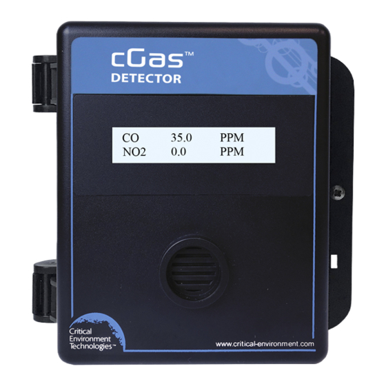
- Page 1 Operation Manual Rev. A | 2020.03 cGas Detector Digital Transmitter www.critical-environment.com...
- Page 2 Rev. A | 2020.03 NEED MORE INFORMATION? This is the Operation Manual for the cGas Detector Digital Transmitter. If you would like it in pdf form, please scan the QR code on the back cover page of this booklet or you can download it from our website: https://www.critical-environment.com/media/download/manuals/CGAS-D-...
-
Page 3: Table Of Contents
Rev. A | 2020.03 cGas Detector Digital Transmitter - Operation Manual TABLE OF CONTENTS 1 POLICIES .......................6 1.1 Important Note ..................6 1.2 Warranty Policy ..................7 1.3 Service Policy ..................8 1.4 Copyrights ....................9 1.5 Disclaimer ....................9 1.6 Revisions .................... - Page 4 Detector Digital Transmitter - Operation Manual Rev. A | 2020.03 6.3.2 Display Confi gurations ..............26 6.3.3 Display or Hide Line 1 and/or 2 ............ 27 6.4 Alarm Status, Fault Detection and Communication Failure Alerts ... 28 6.5 Enable / Disable Channels ..............29 6.6 Setting Channel Alarm Setpoints, Direction and Hysteresis .....
- Page 5 Rev. A | 2020.03 cGas Detector Digital Transmitter - Operation Manual 9 CALIBRATION ....................49 9.1 Calibration Specifi cations ..............49 9.1.1 Gas ..................... 49 9.1.2 Regulators & Flow ................50 9.1.3 Adapters ................... 50 9.1.4 Calibration Frequency ..............50 9.1.5 Gas Testing Frequency (Bump Testing) ........51 9.1.6 Sticky Gases..................
-
Page 6: Policies
Detector Digital Transmitter - Operation Manual Rev. A | 2020.03 1 POLICIES 1.1 Important Note Read and understand this manual prior to using this instrument. Carefully read the warranty policy, service policy, notices, disclaimers and revisions on the following pages. -
Page 7: Warranty Policy
Rev. A | 2020.03 cGas Detector Digital Transmitter - Operation Manual 1.2 Warranty Policy Critical Environment Technologies Canada Inc. (the manufacturer) warrants this gas monitoring instrument, (excluding sensors, battery packs, batteries, pumps and fi lters), to be free from defects in materials and workmanship for a period of two years from the date of purchase from our facility. -
Page 8: Service Policy
Detector Digital Transmitter - Operation Manual Rev. A | 2020.03 1.3 Service Policy CETCI maintains an instrument service facility at the factory. Some CETCI distributors / agents may also have repair facilities; however, CETCI assumes no liability for service performed by anyone other than CETCI personnel. -
Page 9: Copyrights
Rev. A | 2020.03 cGas Detector Digital Transmitter - Operation Manual 1.4 Copyrights This manual is subject to copyright protection; all rights are reserved. Under international and domestic copyright laws, this manual may not be copied or translated, in whole or in part, in any manner or format, without the written permission of CETCI. -
Page 10: Introduction
2 INTRODUCTION 2.1 General Description Thank you for purchasing our cGas Detector Transmitter. The cGas Detector is a one or two channel gas detection transmitter that offers fl exible customization options with the purpose of meeting your specifi c application and budgetary requirements. -
Page 11: Key Features
Rev. A | 2020.03 cGas Detector Digital Transmitter - Operation Manual The sensors utilized in this device are accurate enough to measure to Occupational Health & Safety (OHS) hazardous levels for toxic gases. The transmitter operates by diffusion. 2.2 Key Features •... -
Page 12: Instrument Specifications
Detector Digital Transmitter - Operation Manual Rev. A | 2020.03 Option -LT is a low temperature package with OLED display and internal heater for cold environment applications down to -40°C / -40°F • Available with all models except CGAS-D-EETO Option -RHT is an RH &... - Page 13 Rev. A | 2020.03 cGas Detector Digital Transmitter - Operation Manual Conduit Entry Points 12.7 mm / 1/2 in diameter 4.47 mm / 0.175 in diameter Mounting Holes maximum head diameter 8 mm / 0.32 in, #8 or 4 mm screw USER INTERFACE 2-line by 16 character graphic LCD, user confi...
- Page 14 Detector Digital Transmitter - Operation Manual Rev. A | 2020.03 INPUT/OUTPUT Modbus® ID: 100 (default, confi gurable) Communication Baud rate: 19,200 (default, confi gurable) Modbus® RTU Data bits: 8 (version 1.1b3) Start bits: 1 RS-485 Stop bits: 1 Parity: none BACnet®...
- Page 15 Rev. A | 2020.03 cGas Detector Digital Transmitter - Operation Manual Pollution Degree Degree 2 Altitude below 2,000 m CERTIFICATION Model: CGAS-D-XXX S/N: CGASD1807B00010 Rating: 16-30 VDC, 3W, Class 2 12-27 VAC, 50-60 Hz, 3VA, Class 2 CERTIFIED FOR ELECTRIC SHOCK & ELECTRICAL FIRE HAZARD ONLY. LA CERTIFICATION ACNOR COUVRE UNIQUEMENT LES RISQUES DE CHOC ELECTRIQUE ET D’INCENDIE D’ORIGINE ELECTRIQUE.
-
Page 16: Enclosure Dimensions
Detector Digital Transmitter - Operation Manual Rev. A | 2020.03 3.2 Enclosure Dimensions Above dimensions are shown with optional splash guard. Without splash guard, thickness is 71 mm / 2.8 in. The area required for enclosure door to be open 90 degrees is 178 mm / 7.0 in or 254 mm / 10.0 in for fully open. -
Page 17: Sensor Specifications
Rev. A | 2020.03 cGas Detector Digital Transmitter - Operation Manual 4 SENSOR SPECIFICATIONS 4.1 Single Channel Gas Sensor Options Electrochemical Sensors Part Number Range Lifespan Ammonia (NH CGAS-D-NH3 0 - 500 ppm ~2 yrs Carbon Monoxide (CO) CGAS-D-CO 0 - 200 ppm... - Page 18 Detector Digital Transmitter - Operation Manual Rev. A | 2020.03 Phosphine (PH CGAS-D-PH3 0 - 5 ppm ~2 yrs Silane (SiH CGAS-D-SIH4 0 - 20 ppm ~2 yrs Sulphur Dioxide (SO CGAS-D-SO2 0 - 20 ppm ~2 yrs Refrigerant Sensors...
-
Page 19: Dual Channel Gas Sensor Options
Rev. A | 2020.03 cGas Detector Digital Transmitter - Operation Manual PID Sensors Part Number Range TVOC CGAS-D-SPL 0 - 30 ppm usage / application TVOC CGAS-D-SPH 0 - 300 ppm dependent Infrared Sensors Part Numbers Range Lifespan CGAS-D-CO2-5K 0 - 5,000 ppm... -
Page 20: Calibration Extending Firmware (Cef) And Sensor Aging
UL2075 approved CO sensor 4.3 Calibration Extending Firmware (CEF) and Sensor Aging The cGas Detector with integral electrochemical sensor(s) have been programmed with our CEF. This fi rmware takes into consideration the aging of the electrochemical CO and NO2 sensors so that less frequent calibrations are required in less-critical applications such as parking garages. -
Page 21: Instrument Features
Rev. A | 2020.03 cGas Detector Digital Transmitter - Operation Manual 5 INSTRUMENT FEATURES 5.1 Exterior Enclosure Œ • • • Ž Œ NUMBER FEATURE FUNCTION Secures door to base and allows Œ Door Hinge easy opening and closing LCD display (standard display) •... -
Page 22: Interior System Layout
Detector Digital Transmitter - Operation Manual Rev. A | 2020.03 5.2 Interior System Layout Œ • Œ Œ Ž • • NUMBER FEATURE FUNCTION Access menu options and program Programming Œ functions using buttons inside the Buttons enclosure. (Arrow up, Enter, Arrow down) -
Page 23: System Operation & Configuration
The cGas Detector continuously monitors target gas concentrations on one or two confi gured channels. It must be connected to a controller, control panel or BAS / BMS / DDC system; the cGas Detector is not a standalone gas detection system. - Page 24 Detector Digital Transmitter - Operation Manual Rev. A | 2020.03 position. Continue until the full code is entered and press ENTER when fi nished. CODE NAME DESCRIPTION • Test Reading 0001 Test Menu • Test Relay (if Option -RLY is installed) If confi...
-
Page 25: Display Settings
Rev. A | 2020.03 cGas Detector Digital Transmitter - Operation Manual • Selected Channel • Set Calibration Gas • Calibrate Zero • Calibrate Span 3032 Calibrate Menu • Temperature Offset* • Humidity Offset* • Temperature Units* *displayed only if -RHT option is installed 6.3 Display Settings... -
Page 26: Display Confi Gurations
Detector Digital Transmitter - Operation Manual Rev. A | 2020.03 DisplayMenu Brightness Press Enter Press ENTER. Use the UP button to change the numeric value. Move to the next digit by pressing ENTER. When fi nished, press ENTER to confi rm and Exit. -
Page 27: Display Or Hide Line 1 And/Or 2
Rev. A | 2020.03 cGas Detector Digital Transmitter - Operation Manual 6.3.3 Display or Hide Line 1 and/or 2 The display can show a maximum of two lines of data. Choose what you want to see on line 1 and line 2 from four available options. -
Page 28: Alarm Status, Fault Detection And Communication Failure Alerts
High alarm high The cGas Detector has built in fault detection, and in the event of a problem with the measurement circuitry the transmitter will indicate a fault condition on the display. Normal operation will resume once the fault condition has been corrected. -
Page 29: Enable / Disable Channels
Rev. A | 2020.03 cGas Detector Digital Transmitter - Operation Manual 6.5 Enable / Disable Channels This setting allows you to enable or disable the channel(s) that are already confi gured in the device. If the device has one channel, you can enable or disable that one channel. -
Page 30: Setting Channel Alarm Setpoints, Direction And Hysteresis
6.6 Setting Channel Alarm Setpoints, Direction and Hysteresis The cGas Detector is confi gurable as a one or two channel gas detector and each channel can be confi gured with LOW, MID and HIGH gas alarm setpoints in an ascending or descending direction. - Page 31 Rev. A | 2020.03 cGas Detector Digital Transmitter - Operation Manual Most installations will use the following factory default alarm setpoints: STANDARD HIGH SENSOR GAS TYPE RANGE ALARM ALARM ALARM Carbon Dioxide (CO 0 - 5,000 ppm 1,000 ppm 1,250 ppm...
- Page 32 Detector Digital Transmitter - Operation Manual Rev. A | 2020.03 stop. If the alarm setpoint is 100 ppm and the hysteresis is 5 ppm, when the gas concentration reaches or exceeds 100 ppm, the alarm will come on. The alarm will stay on until the gas concentration reduces to 95 ppm (5 ppm below the alarm setpoint).
- Page 33 Rev. A | 2020.03 cGas Detector Digital Transmitter - Operation Manual Selected Alarm >Mid Alarm Press the Up button until you see Alarm Setpoint, confi rm the desired number is showing. Alarm Setpoint 25 PPM If you want to enter a different alarm setpoint, press Enter and use the UP and ENTER buttons to change the number.
-
Page 34: Relay Function (Models With Option -Rly)
NOTE: The relay option is not currently available with CO gas confi gurations. The cGas Detector can be ordered with Option -RLY, an SPDT dry contact relay rated 30 volts, 2 amps max. The relay components are connected to a circuit board that plugs into one of the plug &... -
Page 35: Change Units ( C Or F) Of Temperature Readings
6.8 Change Units ( C or F) of Temperature Readings NOTE: This menu item only applies if the cGas Detector has the -RHT option installed. You can change the factory confi gured temperature unit type from Celsius to Fahrenheit (or vice versa) very easily. - Page 36 F) of Temperature Readings. The temperature and relative humidity sensors come pre-calibrated from the factory. If you fi nd that the readings on the cGas Detector are higher or lower than another measurement device, you can adjust the reading by setting an offset value so the reading is more accurate.
-
Page 37: Test Functions
(within the range of the sensor) that will be sent over the digital network to test the connection and confi gured responses between the cGas Detector and the DDC/BAS. You can do the same for relative humidity and temperature if the -RHT option is installed. -
Page 38: Test Relay (Models With Option -Rly)
Detector Digital Transmitter - Operation Manual Rev. A | 2020.03 • Gas Type (ie. NO2) • Temperature • Humidity Press the UP button to fi nd Test Reading. To make a change, press ENTER and then use the UP, DOWN and ENTER buttons to enter the value. -
Page 39: Modbus And Bacnet Configuration
>Untripped When fi nished, press ENTER and then UP to Exit. 7 MODBUS AND BACNET CONFIGURATION The cGas Detector can be changed from Modbus® to BACnet® or vice versa in the fi eld. 7.1 Changing Communication Type (Modbus®/BACnet®) in the... -
Page 40: Confi Guring Modbus® Settings
Detector Digital Transmitter - Operation Manual Rev. A | 2020.03 Press ENTER and the cGas Detector will power off and on. This will cause a brief interruption in communications if the cGas Detector is on a network. NOTE: If you change the Comm Type, make sure you make the necessary changes to the corresponding MAC, Baud and Instance ID as appropriate. -
Page 41: Change Modbus® Baud Rate
Rev. A | 2020.03 cGas Detector Digital Transmitter - Operation Manual From the main display, press ENTER. Enter passcode 1001 using the UP button and ENTER button. Enter Password 1001 Press ENTER to access the Basic Menu. Basic Menu Press Enter The Comm Type displayed should be MODBUS. -
Page 42: Modbus® Holding Registers
Modbus® holding registers, please contact CETCI for assistance. 7.3 Confi guring BACnet® Settings The cGas Detector can be confi gured with BACnet® output to communicate with a BAS, DDC or similar control panel. 7.3.1 Change BACnet® MAC Address The factory set default BACnet®... -
Page 43: Change Bacnet® Instance Id
Rev. A | 2020.03 cGas Detector Digital Transmitter - Operation Manual From the main display, press ENTER. Enter passcode 1001 using the UP button and ENTER button. Enter Password 1001 Press ENTER to access the Basic Menu. Basic Menu Press Enter The Comm Type should be BACnet. -
Page 44: Change Bacnet® Baud Rate
Detector Digital Transmitter - Operation Manual Rev. A | 2020.03 Comm Type Instance ID BACnet 270100 Press ENTER. Use the UP button to enter the numeric value. Move to the next digit by pressing ENTER. When fi nished, press ENTER to confi rm and Exit. -
Page 45: Bacnet® Pics Information
ENTER to Exit. 7.3.4 BACnet® PICS Information Critical Environment Technologies Canada Inc. (CETCI) has been granted the BACnet® Testing Laboratories (BTL) certifi cation for the CGAS Detector Family upon passing the BTL requirements for the BACnet® Smart Actuator (B-SA) designation. -
Page 46: How To Replace Or Add A New Smart Sensor Board
Detector Digital Transmitter - Operation Manual Rev. A | 2020.03 8.1 How to Replace or Add a New Smart Sensor Board Smart board replacement sensors arrive pre-calibrated and factory confi gured. After you physically replace the smart sensor board, you have to Read the data stored in the new sensor board up to the main board, overwriting the old sensor’s calibration information. -
Page 47: Read From Sensor
Rev. A | 2020.03 cGas Detector Digital Transmitter - Operation Manual When installing a second smart sensor after initially ordering a single smart sensor model, you will need to remove the center circular cut out of the foam in the second sensor vent area before installing the smart board. -
Page 48: Write To Sensor
Every time a change is made on the cGas Detector, the main circuit board saves the change to the smart sensor board automatically. However, there may be instances when you may want to force save the changes to the smart sensor board, such as if the memory of the smart sensor board gets corrupted. -
Page 49: Calibration
fi rst, followed by zeroing. • Carbon dioxide sensors require 99.9% nitrogen (N2) for a true zero. If the cGas Detector has a splash guard you will need to fl ow the nitrogen for approximately 4 minutes BEFORE you enter the Calibrate Zero menu. -
Page 50: Regulators & Flow
9.1.3 Adapters The proper calibration adapter should be utilized to allow the gas to properly diffuse around the sensor. The calibration adapter plug for a cGas Detector with an internal sensor without a splash guard is part number CET-7000-CAP. For a cGas Detector with a splash guard, use part number CET-4700-SCC or use the Cal Clip hands free adapter, part number CET-SGC. -
Page 51: Gas Testing Frequency (Bump Testing)
Phosphine (PH ) adhere to surfaces such as tubing and splash guards. The cGas Detector can be ordered with a special splash guard if confi gured with a sticky gas sensor. When calibrating with sticky gases we suggest using Tefl on lined tubing so the gas doesn’t adhere to the tubing, reducing the concentration of the fl... -
Page 52: Set Calibration Gas Value
Detector Digital Transmitter - Operation Manual Rev. A | 2020.03 9.2.1 Set Calibration Gas Value Check to make sure that the calibration gas value confi gured in the device matches the gas concentration of the calibration gas cylinder you are using. -
Page 53: Zero (Null) Calibration
Rev. A | 2020.03 cGas Detector Digital Transmitter - Operation Manual The factory default calibration gas concentrations are: SENSOR GAS TYPE CALIBRATION GAS LEVEL* Carbon Dioxide (CO 1,000 ppm Carbon Dioxide (CO 1.0 % VOL Carbon Monoxide (CO) 100 ppm... -
Page 54: Span Calibration
Detector Digital Transmitter - Operation Manual Rev. A | 2020.03 Calibrate Menu Press Enter In the Selected Channel menu, confi rm the desired channel is showing. Selected Channel If you want to choose a different channel, press ENTER and use the UP button to scroll to the next channel. - Page 55 Rev. A | 2020.03 cGas Detector Digital Transmitter - Operation Manual NOTE: To exit the Span Calibration at any time, press ENTER. From the main display, press ENTER. Enter passcode 3032 using the UP button and ENTER button. Enter Password 3032 Press ENTER to access the Calibrate Menu.
-
Page 56: Troubleshooting Calibration
Use a slight twisting motion as you gently push the calibration adapter plug (p/n: CET-7000-CAP) into the sensor opening. If it is hard to insert, moisten the O-ring seal slightly then try re-inserting it. If the splash guard is installed, use the... -
Page 57: Zero Fault
NOTE: Response time will be slower with the splash guard installed. 9.3.2 Zero Fault If the zeroing process fails, the cGas Detector will show a Zero fault. This will happen if the ambient gas readings are at an unacceptable level due to not enough clean air - there is enough residual target gas in the environment or other gases that are interfering with the sensor seeing oxygen. -
Page 58: Span Override
Detector Digital Transmitter - Operation Manual Rev. A | 2020.03 9.3.5 Span Override During the Span calibration, readings are taken and from the results sensitivity is calculated and compared to the original sensitivity of the sensor at the time of installation. - Page 59 Rev. A | 2020.03 cGas Detector Digital Transmitter - Operation Manual to scroll to the next channel. Press ENTER and continue. Press Enter to continue. Use the UP button to fi nd Calibrate Span. Press ENTER. Calibrate Span 4000 AD Confi...
- Page 60 Detector Digital Transmitter - Operation Manual Rev. A | 2020.03 Stabilizing Spanning 1961AD 1957AD Span Success 1956 When the process has fi nished and the Span calibration was accepted, remove the cylinder of span gas. Refer to Section 9.3.5 Span Override if the Span calibration was not successful.
-
Page 61: Accessories
10.2 Calibration Adapter Clip “Cal Clip” (p/n: CET-SGC) To calibrate a cGas Detector with a factory installed splash guard (Option -S), attach the Cal Clip around the splash guard to allow the use of both hands during calibration. The small barb hose fi tting accommodates standard or Tefl... -
Page 62: Splash Guard For Sticky Gases (Option -Sn)
Detector Digital Transmitter - Operation Manual Rev. A | 2020.03 NOTE: The Cal Clip is designed to prevent entry or exit of air except via the hose barb fi tting, therefore it must be removed during normal operation or else the gas readings will not be accurate. -
Page 63: Calibration Kit
Rev. A | 2020.03 cGas Detector Digital Transmitter - Operation Manual Material 16 gauge galvanized steel Weight 800 g (28 oz) Size 178 mm W x 160 mm H x 91 mm D (7.0” W x 6.3” H x 3.6” D) 10.5 Calibration Kit (p/n: CET-715A-CK1) -
Page 64: Maintenance
Gas cylinders cannot be shipped from Canada to other countries, including the USA. 11 MAINTENANCE The cGas Detector transmitter requires virtually no maintenance other than regular calibration of the sensor(s). There are no replaceable components except the sensors. - Page 65 Detector Digital Transmitter - Operation Manual Display shows “ZERO FAULT” message. The cGas Detector is unable to complete the zeroing (null) process. If using ambient air, make sure there are no contaminants or residual target gas in the air. If using a cylinder of oxygen, use 20.99% volume, scrubbed of hydrocarbons.
- Page 66 Detector Digital Transmitter - Operation Manual Rev. A | 2020.03 • Check to make sure the device has a unique ID assigned to it, which is made up of the MAC ID and the Base ID. • Check that local area network wiring is correct, especially the A and B lines to make sure they are not swapped between devices on the network.
- Page 67 Rev. A | 2020.03 cGas Detector Digital Transmitter - Operation Manual cGas cannot communicate with the CO sensor even though it can communicate with the Communication smart board. Power cycle or replace the sensor Fault smart board. The internal smart sensor board gainPOT chip POT chip has has failed.
- Page 68 CGAS-D-20200312-Rev-A Unit 145, 7391 Vantage Way, Delta, BC V4G 1M3 Canada Tel: +1.604.940.8741 Toll Free: +1.877.940.8741 www.critical-environment.com © 2020 All rights reserved. Data subject to change without notice.
Need help?
Do you have a question about the cGas Detector and is the answer not in the manual?
Questions and answers