Advertisement
Quick Links
Advertisement

Related Manuals for Athena GET SL1

Summary of Contents for Athena GET SL1
- Page 1 ENGLISH DATA LOGGER User Manual...
- Page 2 The content of this document, nor parts of it, may be reproduced, transferred, distributed or stored in any form without the written permission of GET by Athena. GET reserves the right to make changes to the content of this manual without notice.
- Page 3 Changing the auto power off time 12.8.2 Changing the GPS dynamic 12.8.3 Changing the brightness of the SL1 LEDs 12.8.4 Turning off the SL1 Data Logger 12.9 Changing the Lynxlog settings SL1 DATA LOGGER TECHNICAL SPECIFICATIONS ANNEX 1 ACQUISITION SETUP DETAILS SET INFO www.getdata.it sales.get@athena.eu...
- Page 4 APPLICATION ROAD CAN BUS + EXT. SENSORS: SL1 , RX1PRO ECU, D30 DASH APPLICATION ROAD CAN BUS + EXT. SENSORS: SL1 , ECULMB ECU (e.g. YZF-R25/ R3), D30 DASH ANALOGUE CONNECTION LC1-EVO SENSORS SL1 FOR TYPE ANALOGUE SENSORS IC SENSORS www.getdata.it sales.get@athena.eu...
- Page 5 Therefore please read this manual as we are sur e that it can help you to properly use your new GET by Athena device. Thanks to GPS technology, the devices in the SL1 Data Logger family are able to acquire not only signals from the sensors connected to them, but also vehicle trajectories and speed.
- Page 6 RUN – Data acquisition that has a progressive number and a date. SETUP – SL1 Data Logger configuration file. SL1 – Commercial name of the Athena data acquisition device. TPS – Accelerator position sensor. USB – Communication port with wired communication.
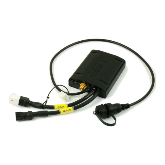
- Page 7 SL1 Data Logger 1 SL1 wiring harness 1 GPS Antenna 1 USB data cable (mini - USB) for connection to the PC 1 USB flash drive Note: The content of the kit may vary depending on the version. www.getdata.it sales.get@athena.eu...
- Page 8 The GPS uses a stochastic algorithm and is strongly influenced by the quality of the received signal. In the case of magnetic or environmental interference, data quality is not guaranteed. There must be a minimum number of 5 received satellites to guarantee the quality of the lap times. www.getdata.it sales.get@athena.eu...
- Page 9 MANAGER SOFTWARE SENSOR Vehicle SL1 DATA LOGGER SIGNALS & DATA FROM CAN BUS DATA ANALYSIS VIA WINTAX The SL1 Data Logger can be connected to the vehicle (or the sensors) using the Annex 3 specific cable (refer to www.getdata.it sales.get@athena.eu...
-
Page 10: Installing The Gps Antenna
SL1 DATA LOGGER User Manual Rev. AD ENGLISH SL1: INSTALLATION The SL1 Data Logger is designed to be easily installed in all vehicles. With the dedicated cables, the Athena Evolution ECU (example RX1PRO) can be directly connected via CAN bus. Annex 2 Annex 3 For electrical connections, see of this manual. - Page 11 ATTENTION: INCORRECT INSTALLATION COULD CAUSE PERSONAL INJURY OR PROPERTY DAMAGE SL1: FRONT VIEW 1: STATUS LED - Green 2: GPS LED - Yellow 3: DIAGNOSTICS LED - Red 4: GPS antenna connector 5: MAIN connector 6: EXP connector 7: USB connector www.getdata.it sales.get@athena.eu...
-
Page 12: Installing The Software
If you want to install the software manually, follow these instructions: Proceed as follows to install the LynXLog software: • Double click the software installer icon: LynXLog_GET_Install_<Version>.exe Accept the terms of the license and then press Next> www.getdata.it sales.get@athena.eu... - Page 13 SL1 DATA LOGGER User Manual Rev. AD ENGLISH Leave all the selected components and press Next> • www.getdata.it sales.get@athena.eu...
- Page 14 SL1 DATA LOGGER User Manual Rev. AD ENGLISH Proceed with the installation, following the instructions shown in the following windows: • 1- LynXLog www.getdata.it sales.get@athena.eu...
- Page 15 SL1 DATA LOGGER User Manual Rev. AD ENGLISH 2- Driver www.getdata.it sales.get@athena.eu...
- Page 16 SL1 DATA LOGGER User Manual Rev. AD ENGLISH 3- WinTAX 4- Finish www.getdata.it sales.get@athena.eu...
-
Page 17: Software Update
SL1 DATA LOGGER User Manual Rev. AD ENGLISH 7.1.1 HOW TO ACTIVATE THE WINTAX4 JUNIOR LICENSE WinTAX4 Junior requires a valid user license. tech@athena.eu This license must be requested via e-mail to: The e-mail must contain: • WinTAX Registration ID (shown when WinTAX is executed) •... - Page 18 If you press Yes SL1 will be updated and when the update process is complete, it will reboot and will be ready to be used. • If you press No the update will be interrupted and the procedure will restart the next time you want to update the SL1 Data Logger. www.getdata.it sales.get@athena.eu...
- Page 19 SL1 DATA LOGGER TO ACQUISITION (Base Directory) IN THE VEHICLE PARAMETERS (CHANNELS, TRIGGERS, INFO ETC.) Normal use CONNECT SL1 DATA CONFIGURE THE DATA LOGGING DATA DOWNLOAD DATA ANALYSIS LOGGER TO THE PC ACQUISITION WITH WITH PARAMETERS LYNXLOG WINTAX (IF NECESSARY) www.getdata.it sales.get@athena.eu...
- Page 20 Green GPS signal OK Yellow SYSTEM Flashing Acquisition in progress DIAGNOSTICS System OK SYSTEM UPDATE (OTA FUNCTION AND ACQUISITION CONFIGURATION) TYPE STATUS DESCRIPTION OTA Update Green GPS signal OK Yellow SYSTEM Acquisition in progress DIAGNOSTICS Flashing System OK www.getdata.it sales.get@athena.eu...
- Page 21 The LynXLog home page is divided into 3 areas: LYNXLOG HOME PAGE AREA FUNCTION Used to move through LynXLog without using the function NAVIGATION BAR buttons FUNCTION BUTTONS They are used to access the LynXLog functions STATUS BAR Contains the icons that indicate the system status www.getdata.it sales.get@athena.eu...
- Page 22 Opens the track creation page, where personal tracks can be created, TRACK loaded and edited. Opens the system configuration page where it is possible to change LYNXLOG SETUP the predefined software folders and the size of the character used on the interface. www.getdata.it sales.get@athena.eu...
-
Page 23: Usb Connection
PC. may take up to 30 seconds if the system was off). Logger. NOTE: THE SL1 DATA LOGGER CAN BE POWERED VIA THE USB CABLE, THIS PERMITS DOWNLOADING DATA WITHOUT THE NEED FOR AN AUXILIARY POWER SUPPLY www.getdata.it sales.get@athena.eu... - Page 24 GK-SL1-0001 is required • Connect the SL1 wiring to a 12V power supply, the wiring must also be connected to the main SL1 cable chapter 7 • Wait for the green LED to turn on (see www.getdata.it sales.get@athena.eu...
- Page 25 Open the Windows network manager: • Select the ssid of the SL1 Data Logger to which you want to connect • Enter the WIFI password, which can be found on the label glued on the SL1 Data Logger: www.getdata.it sales.get@athena.eu...
- Page 26 • Start LynXLog • Open the Data page by pressing the Data button or press the icon on the navigation bar • Press the text located below Base Directory in the Data Path column and select the desired path: www.getdata.it sales.get@athena.eu...
- Page 27 Run_name: this is the last subfolder of the storage path – its value is set by “Run_“ followed by the progressive number of the session created by the SL1 Data Logger. chapter 1 Annex 1 For more information, refer to www.getdata.it sales.get@athena.eu...
- Page 28 Open the Data page by pressing the Data button or pressing the icon on the navigation bar Press a single Run or press the Sel. All button to select all the data saved in the SL1 Data • Logger memory Press the Download button to start downloading the sessions • www.getdata.it sales.get@athena.eu...
- Page 29 Open the Data page by pressing the Data button or pressing the icon on the navigation bar Press a single Run or press the Sel. All button to select all the data saved in the SL1 Data • Logger memory www.getdata.it sales.get@athena.eu...
- Page 30 Which of the signals connected to the physical inputs of the SL1 Data Logger to acquire and how to acquire them. All of the options can be found on the Log Config page: Annex 1. For more information about setup configuration, see www.getdata.it sales.get@athena.eu...
- Page 31 > Read Conf. to import the setup from the SL1 Data Logger: • Press the button Once the setup was imported, its components will be listed in the Config Channel Tree, press • an element to open its panel www.getdata.it sales.get@athena.eu...
- Page 32 Select the setup file to open and press open • Once the setup is open its components will be listed in the Config Channel Tree column, press • an element to open its panel. www.getdata.it sales.get@athena.eu...
- Page 33 During the procedure for sending the configuration, the red LED flashes a few times which indicates that the SL1 Data Logger is applying the configuration. • At the end of the operation, a message is displayed to indicate that the procedure is complete. www.getdata.it sales.get@athena.eu...
-
Page 34: Changing The Setup
CAN Bus port EXP (on the EXP connector) GPS channels (latitude, longitude, number of received satellites, GPS speed, etc.) Accelerometers, gyroscopes • By Pressing one of the options opens the relative table, edit the desired parameters (see Annex 1 www.getdata.it sales.get@athena.eu... - Page 35 Once the change to the setup is complete, it is important to save it to a file, following these steps: Press the Save Conf. button in the Actions column • • Select the folder where the setup file should be saved, select the name and then press save. www.getdata.it sales.get@athena.eu...
- Page 36 Open the page by pressing the Monitor function button or by pressing the icon • on the navigation bar 12.6.1 ADDING A CHANNEL TO THE CHANNEL MONITOR LIST • Press the box next to the channel you want to see in real time in the Monitor Channels Tree column www.getdata.it sales.get@athena.eu...
- Page 37 At this point, the current value of the channel will be displayed. It changes in real time as the input signal changes. • Repeating this procedure, it is possible to add a total of 8 channels to be displayed in real time. www.getdata.it sales.get@athena.eu...
- Page 38 To remove a channel from the channel monitor list, press the button to the left of the name of the channel • Another way to remove the channel from the channel monitor list is to press the ticked box in the Monitor Channel Tree column. www.getdata.it sales.get@athena.eu...
- Page 39 MONITOR LIST • To calibrate a channel on the Channel Monitor list press the button chapter 6 of Annex 1 More information about calibration is available in ATTENTION: THE SET 0 OPTION IS ONLY AVAILABLE FOR SUSPENSION CHANNELS www.getdata.it sales.get@athena.eu...
- Page 40 Press the Set 0 button to set the zero position, the value of the channel in mm will become • zero. • Send the new setup to the SL1 Data Logger, pressing Set. Conf > in the actions column. ATTENTION: THE SET 0 FUNCTION IS ONLY AVAILABLE FOR SUSPENSION TYPE CHANNELS www.getdata.it sales.get@athena.eu...
- Page 41 The yellow SL1 Data Logger LED will start to flash, indicating that acquisition is in progress. • To stop acquisition, press the Man. Rec. button again chapter 12.3 • At this point, there should be a new session on the Runs list, refer to download it. www.getdata.it sales.get@athena.eu...
- Page 42 Read the current system settings by pressing Refresh • Set the auto power off time by pressing POWER OFF in the Actions column • • Set the brightness of the SL1 Data Logger LEDs by pressing LEDs in the System options column. www.getdata.it sales.get@athena.eu...
- Page 43 If the SL1 Data Logger is not in acquisition mode, is not connected to a PC and is not powered by an external power supply, it will turn off automatically after the Auto Power Off time. Proceed as follows: Press POWER OFF in the System options column • www.getdata.it sales.get@athena.eu...
- Page 44 SL1 DATA LOGGER User Manual Rev. AD ENGLISH Select a time option from among those available and then press Set Device in the Actions • column to send the configuration to the SL1 Data Logger. www.getdata.it sales.get@athena.eu...
- Page 45 SL1 DATA LOGGER User Manual Rev. AD ENGLISH 12.8.2 CHANGING THE GPS DYNAMIC To improve the GPS trajectories it is possible to select the GPS dynamic that best suits to the type of trajectory being acquired. Press GPS in the System options column • www.getdata.it sales.get@athena.eu...
- Page 46 SL1 DATA LOGGER User Manual Rev. AD ENGLISH • Press one of the available icons to select the dynamic. Press Set Device in the Actions column to send the changed dynamic to the SL1 Data Logger • www.getdata.it sales.get@athena.eu...
- Page 47 12.8.3 CHANGING THE BRIGHTNESS OF THE SL1 LEDs Proceed as follows to adjust the brightness of the LEDs on the SL1: • Press LEDs in the System options column • Press one of the options to regulate the LED brightness www.getdata.it sales.get@athena.eu...
- Page 48 If the residual charge of the battery in the SL1 Data Logger is insufficient (external/USB power supply not connected) then all of its LEDs will flash and then it will turn off. This can occur even if the SL1 Data Logger is acquiring data. www.getdata.it sales.get@athena.eu...
- Page 49 If you want to change the size of the LynXLog text, press TEXT SIZE in the Software options column Press any point along the bar in the TEXT SIZE column to change the size of the software • text www.getdata.it sales.get@athena.eu...
- Page 50 • • Track Archive (predefined folder for the tracks) Log Config Archive (predefined folder for the SL1 Data Logger configurations) • This can be done on the Default Path Page: Press DEFAULT PATH in the Software options column www.getdata.it sales.get@athena.eu...
- Page 51 SL1 DATA LOGGER User Manual Rev. AD ENGLISH • Press one of the paths you want to change to select it. A window will open where the desired folder can be selected. Confirm it once selected. www.getdata.it sales.get@athena.eu...
- Page 52 2 2.0 High Speed ports (125 – 250- 500 kb/s, CAN port: 1Mb/s) Intel/Motorola format Serial port: 1 communication port RS232 Connectivity: ✓ USB 2.0 port: ✓ BLE: ✓ (model GK-SL1-0001 only) WiFi : Software: SL1 Data Logger Tool and WinTAX4 analysis Desktop software software www.getdata.it sales.get@athena.eu...
- Page 53 Channels related to Acquisition the GPS module Each group of options is available by pressing the relative item in the Config Channel Tree column. The following instructions assume that the reader has opened a valid setup (see chapter 12.5.1 12.5.2 www.getdata.it sales.get@athena.eu...
- Page 54 Vehicle Name: this is the third subfolder of the storage path – its value is set by the Vehicle on the setup INFO panel. • Run_name: this is the last subfolder of the storage path – its value is set by “Run_“ followed by the progressive number of the session created by the SL1 Data Logger. www.getdata.it sales.get@athena.eu...
-
Page 55: Searching For A Channel
There is a search function that makes it easier to search for a channel in the Config Channel Tree. Press the text in the Find Channel field and scroll the list of all the channel names. Otherwise enter the name of the channel you are looking for and it will be filtered. www.getdata.it sales.get@athena.eu... - Page 56 If the channel selected for starting acquisition is not Manual, the table will be completed with all the options necessary for configuring automatic acquisition: Configure as necessary and save the setup to a file or send it to the SL1 Data Logger when fini- chapters 12.5.3 12.5.5 shed (see www.getdata.it sales.get@athena.eu...
- Page 57 Configure as necessary and save the setup to a file or send it to the SL1 Data Logger when finished (see chapters 12.5.3 12.5.5 * NOTE: the acquisition frequency can be changed directly in the AN/FRQ table www.getdata.it sales.get@athena.eu...
- Page 58 Byte Order: this parameter makes it possible to set the format of the CAN BUS data to one of the following: Intel: Little Endian byte order Motorola: Big Endian byte order ADDING A NEW CAN CHANNEL To add a new channel, press Add Channel in the Config Channel Tree column • www.getdata.it sales.get@athena.eu...
- Page 59 Start bit: this parameter defines the position (in the ID CAN message) that contains the first • bit of data to be associated to the channel. • Length: defines the length of a CAN channel bit. NOTE: this parameter also defines if the channel is signed or unsigned, see below: www.getdata.it sales.get@athena.eu...
- Page 60 Channel description: it contains a channel comment that is displayed when the mouse is moved • over the name of the channel. Configure as necessary and save the setup to a file or send it to the SL1 Data Logger when finished (see chapters 12.5.3 12.5.5 www.getdata.it sales.get@athena.eu...
- Page 61 CAN PORT GET column. The Channel Calibration window will open. Configure as necessary and save the setup to a file or send it to the SL1 Data Logger when fini- chapters 12.5.3 12.5.5 shed (see www.getdata.it sales.get@athena.eu...
- Page 62 If the None calibration option is used, the input data will not be calibrated and will be acquired as is (raw format) • An example of None calibration is shown below: To change the type of calibration, press the Calibration Type drop-down menu and select None www.getdata.it sales.get@athena.eu...
- Page 63 FILE OR SEND IT TO THE SL1 DATA LOGGER (SEE CHAPTERS 12.5.3 12.5.5 TO SEND THE NEW CALIBRATION TO THE SL1 DATA LOGGER: PRESS THE BUTTON TO EXIT THE CHANNEL CALIBRATION PAGE, THEN PRESS THE SET. CONF BUTTON > www.getdata.it sales.get@athena.eu...
- Page 64 For example, if the sensor in the acquired channel is an NTC, the Raw Value will be the output voltage of the NTC whereas the Cal. Value will be the temperature related to that voltage value. Pressing any box in the Calibration Values table makes it possible to change its value. • www.getdata.it sales.get@athena.eu...
- Page 65 SL1 DATA LOGGER User Manual Rev. AD ENGLISH • To add a new line, press • To remove the last line of values, press www.getdata.it sales.get@athena.eu...
- Page 66 FILE OR SEND IT TO THE SL1 DATA LOGGER CHAPTERS 12.5.3 12.5.5 (SEE TO SEND THE NEW CALIBRATION TO THE SL1 DATA LOGGER: PRESS THE BUTTON TO EXIT THE CHANNEL CALIBRATION PAGE, THEN PRESS THE SET. CONF BUTTON > www.getdata.it sales.get@athena.eu...
- Page 67 If the sensor to calibrate is a suspension, this type of calibration must be used. Press Sensor stroke to enter the length of the useful working area of the sensor, • expressed in mm. Change the unit of measurement (unit) and the name of the channel (Channel Name) as • desired www.getdata.it sales.get@athena.eu...
- Page 68 CHAPTERS 12.5.3 FILE OR SEND IT TO THE SL1 DATA LOGGER (SEE 12.5.5 TO SEND THE NEW CALIBRATION TO THE SL1 DATA LOGGER: PRESS THE BUTTON TO EXIT THE CHANNEL CALIBRATION PAGE, THEN PRESS THE SET. CONF BUTTON > www.getdata.it sales.get@athena.eu...
- Page 69 The GPS channels cannot be edited. IMU PANEL The IMU panel can be opened by pressing IMU in the Config Channel Tree IMU column. This panel displays the IMUs acquired by the SL1 Data Logger. The IMU channels cannot be edited. www.getdata.it sales.get@athena.eu...
- Page 70 Run LynXLog and press the Track function button. • Press Click here to search... and enter the name of the city or track (as would be done for • Google Maps): this will focus the map in the indicated location. www.getdata.it sales.get@athena.eu...
- Page 71 Press Add Line in the Actions column: this will make it possible to create a Finish Line. • • Move the map near the finish line (if necessary) and press it to position the first finish line point. www.getdata.it sales.get@athena.eu...
- Page 72 Press the map to create the second finish line point. A finish line will appear with a green arrow indicating the direction of the race. • If the direction is incorrect, it can be changed by pressing the green arrow: www.getdata.it sales.get@athena.eu...
- Page 73 SL1 DATA LOGGER User Manual Rev. AD ENGLISH Enter the name for the track in the Track Name field: • Press Save Track in the Actions column to save the track: • www.getdata.it sales.get@athena.eu...
- Page 74 SENDING A TRACK TO THE SL1 DATA LOGGER • Connect the SL1 Data Logger to the PC and wait for it to be recognised by Lynxlog (see chapter 12.1.1 Press the Log Config function button to open the setup editor: • www.getdata.it sales.get@athena.eu...
- Page 75 SL1 DATA LOGGER User Manual Rev. AD ENGLISH Press the Read Conf. button in the Actions column to download the setup from the SL1 Data Logger: • www.getdata.it sales.get@athena.eu...
- Page 76 Press TRIGGERS in the Config Channel Tree column, the DATA LOG TRIGGERS table and the • LAP TRIGGER SOURCE table will appear • Make sure that the option in the Type column of the LAP TRIGGER SOURCE table is set to GPS (otherwise press the drop-down menu and select it) www.getdata.it sales.get@athena.eu...
- Page 77 SL1 DATA LOGGER User Manual Rev. AD ENGLISH Press the field in the Track column and select a track from the list, then confirm: • Press Set. Conf > to send the new configuration to the SL1 Data Logger: • www.getdata.it sales.get@athena.eu...
- Page 78 Auxiliary power supply and analogue/frequency input negative CAN1L CAN Port EXP - CANL signal CAN1H CAN Port EXP - CANH signal Analogue input 1 (0-5V) 5VAUX Auxiliary power supply output (5VDC) Analogue input 2 (0-5V) Analogue input 3 (0-5V) www.getdata.it sales.get@athena.eu...
-
Page 79: Usb Connector
Front view (The wires exit from the rear) USB Connector Pinout SIGNAL NAME DESCRIPTION USB + USB signal +5V USB N USB signal Data N USB P USB signal Data P USB signal ID USB - USB GND www.getdata.it sales.get@athena.eu... - Page 80 CAN Port GET - CANL signal CAN Port GET - CANH signal Note: this wiring can be used in combination with code GL-167-AB to easily connect a Get ECU as well as a frequency input (e.g. RPM or speed sensor) www.getdata.it sales.get@athena.eu...
- Page 81 NC – not connected • EXP CONNECTOR: must be connected to the EXP connector of the SL1 Data Logger CONNECTOR AN1…AN3: analogue inputs (example: potentiometer, thermocouple, etc.) • CAN EXP CONNECTOR: second CAN port (CAN Port EXP) • www.getdata.it sales.get@athena.eu...
- Page 82 MAIN SL1 CONNECTOR: input for the SL1 Data Logger connection (MAIN connector). • PWR CONNECTOR: to be used to power the system. NOTE: all the connected devices will turn on (e.g ECU, SPA SW...) PWR CONNECTOR PINOUT CONNECTOR/CABLE DESCRIPTION Power supply positive Power supply negative (GNDPWR) www.getdata.it sales.get@athena.eu...
- Page 83 SL1 DATA LOGGER User Manual Rev. AD ENGLISH ANNEX 4 SL1 CONNECTION DIAGRAM The following chapters show some connection examples: RX1/GP1 ECUS - SL1 (BATTERY LESS CONFIGURATION) NOTE: USING OPT., ALL THE CONNECTED DEVICES WILL BE POWERED WITHOUT HAVING TO TURN ON THE ENGINE www.getdata.it sales.get@athena.eu...
- Page 84 SL1 DATA LOGGER User Manual Rev. AD ENGLISH APPLICATION OFFROAD CAN BUS + EXT. SENSORS: RX1/ GP1 ECUS - SL1 (CONF. BATTERY LESS) NOTE: USING OPT.1, ALL THE CONNECTED DEVICES WILL BE POWERED WITHOUT HAVING TO TURN ON THE ENGINE www.getdata.it sales.get@athena.eu...
- Page 85 SL1 DATA LOGGER User Manual Rev. AD ENGLISH APPLICATION ROAD CAN BUS + EXT. SENSORS: SL1 , ECULMB ECU (E.G. YZF-R25/R3), D30 DASH www.getdata.it sales.get@athena.eu...
- Page 86 SL1 DATA LOGGER User Manual Rev. AD ENGLISH APPLICATION ROAD CAN BUS + EXT. SENSORS: SL1 , ECULMB ECU (E.G. YZF-R25/R3), D30 DASH www.getdata.it sales.get@athena.eu...
- Page 87 SL1 DATA LOGGER User Manual Rev. AD ENGLISH ANALOGUE CONNECTION LC1-EVO NOTE: USING OPT.1, ALL THE CONNECTED DEVICES WILL BE POWERED WITHOUT HAVING TO TURN ON THE ENGINE OPT.2 IS REQUIRED ONLY IF FREQUENCY SIGNALS MUST BE ACQUIRED (E.G. FREQUENCY OR WHEEL SPEED) www.getdata.it sales.get@athena.eu...
- Page 88 SL1 DATA LOGGER User Manual Rev. AD ENGLISH SENSORS SL1 FOR TYPE www.getdata.it sales.get@athena.eu...
-
Page 89: Analogue Sensors
Brake pressure sensor sor (TPS) cod. GS-POS-0001 Motor temperature Manual log switch sensor (NTC) cod. GE-DVC-S2-0001 cod. DS40050000 Lambda LC1EVO Linear potentiometer cod. GK-LC1EVO-0001 cod. DS00010000 Exhaust temperature sensor cod. GS-TEM-0002 SENSORI IC RPM signal Speed sensor cod. DS40060000 www.getdata.it sales.get@athena.eu... - Page 90 SL1 DATA LOGGER User Manual Rev. AD ENGLISH NOTES www.getdata.it sales.get@athena.eu...
- Page 91 SL1 DATA LOGGER User Manual Rev. AD ENGLISH NOTES www.getdata.it sales.get@athena.eu...
- Page 92 sales.get@athena.eu...
Need help?
Do you have a question about the GET SL1 and is the answer not in the manual?
Questions and answers