Advertisement
3331051/7
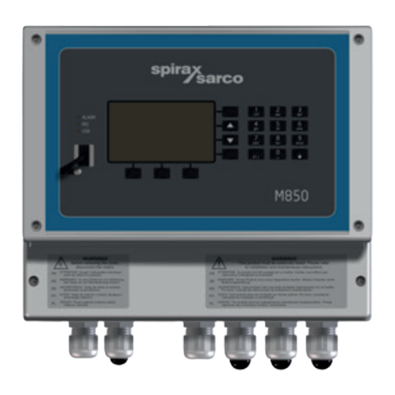
M850-W and M850-P
M850-W-x
M850-P-x
IM-P333-27 EMM Issue 7
Flow Computers
Quickstart Guide
IM-P333-27
2. Safety
information
3. General product
and delivery
information
7. Technical
information
8. Mechanical
installation
9. Electrical
installation
10. Commissioning
Appendix
Please note that this is the
'Quickstart Guide' and that all
relevant Sections for this product
are contained in the main
Installation and Maintenance
Instructions IM-P333-26.
© Copyright 2017
Printed in Poland
EMM Issue 7
1
Advertisement
Table of Contents

Summary of Contents for Spirax Sarco M850-W Series
- Page 1 IM-P333-27 3331051/7 EMM Issue 7 M850-W and M850-P Flow Computers Quickstart Guide 2. Safety information 3. General product and delivery information 7. Technical information M850-W-x 8. Mechanical installation 9. Electrical installation 10. Commissioning Appendix M850-P-x Please note that this is the 'Quickstart Guide' and that all relevant Sections for this product are contained in the main...
-
Page 2: All Rights Reserved
Work(s) may not be used, sold, licensed, transferred, copied or reproduced in whole or in part or in any manner or form other than as expressly granted here without the prior written consent of Spirax-Sarco Limited. Manufacturer Spirax Sarco Limited Runnings Road Cheltenham GL51 9NQ www.spiraxsarco.com... -
Page 3: Safety Information
2. Safety information Safe operation of this product can only be guaranteed if it is properly installed, commissioned, used and maintained by qualified personnel (see the following sections) in compliance with the operating instructions. General installation and safety instructions for pipeline and plant construction, as well as the proper use of tools and safety equipment must also be complied with. -
Page 4: Intended Use
Check that the product is suitable for use with the application. ii) Determine the correct installation situation. iii) Spirax Sarco products are not intended to withstand external stresses that may be induced by any system to which they are fitted. It is the responsibility of the installer to consider these stresses and take adequate precautions to minimise them. - Page 5 The symbols, used on the product, mean: Equipment protected Optically isolated throughout by current source or double insulation sink. or reinforced insulation. Caution, Functional earth Electrostatic (ground) terminal, to Discharge (ESD) enable the product sensitive circuit. to function correctly. Do not touch or Not used to provide handle without electrical safety.
-
Page 6: Protective Clothing
Customers and stockists are reminded that under EC Health, Safety and Environment Law, when returning products to Spirax Sarco they must provide information on any hazards and the precautions to be taken due to contamination residues or mechanical damage which may present a health, safety or environmental risk. - Page 7 3.1 Equipment delivery, handling and storage Factory shipment Prior to shipment, the Spirax Sarco M850 is tested, calibrated and inspected to ensure proper operation. Receipt of shipment Each carton should be inspected at the time of delivery for possible external damage.
- Page 8 3.2 Purpose M850-P and M850-W devices are microprocessor based, universal flow computers designed for measurement of: Flow and heat of steam and water according to IAPWS-IF97, Flow and heat of liquids other than water according to characteristics provided by user, Flow of technical gases.
-
Page 9: Available Options
3.3 Available options Both versions of the M850 series have the same functions and are available as follows: M850-P for panel mounting and is powered by 24 Vdc. M850-W for wall mounting and has been adapted to be powered by 100 / 240 Vac. Additionally, each version can be optionally equipped with one or two analog outputs 4 - 20 mA. -
Page 10: Serviceable Parts
There are no user serviceable parts, battery is good for the life of the product. 3.5.4 Returning faulty equipment Please return all items to your local Spirax Sarco representative. Please ensure all items are suitably packed for transit (preferably in the original cartons). -
Page 11: Technical Information
7. Technical information M850-W and M850-P I type (0 / 4-20 mA current loop analog inputs) 24 Vdc +10% / -20%; max 22 mA per Transmitters supply channel (protected with PTC 50 mA fuse and 100 Ω resistor in series) Maximum input ±... - Page 12 Binary outputs (M850-P-x) Number of outputs Type of outputs 2 pole Solid State Relay Contact rating 0.1 A at 24 Vac/dc (max 42 Vac or 60 Vdc) / (resistive load) SELV Maximum ON 20 Ω resistance Galvanic isolation 250 Vac continuous; 1 500 Vac for 1 minute (optoisolation) RS-485 / 422 Maximum bus...
- Page 13 Enclosure (M850-W-x and M850-W-x-UL) Protection class IP65 (not UL evaluated) Enclosure (M850-P-x) Protection class IP65 / IP20 (not UL evaluated) (front / rear) Environmental conditions Ambient temperature 0 .. +55°C (32 .. 131°F) Relative humidity 5 .. 95% (non-condensing) Altitude ≤...
-
Page 14: Wall Mounting
8. Mechanical installaton Note: Before actioning any installation observe the 'Safety information' in Section 2. M850 The M850 is available for wall mounting M850-W or for panel mounting M850-P. Note: All versions must be fitted away from sources of excessive heat, electrical interference and from all areas liable to flooding. -
Page 15: Other Considerations
Minimum 10 cm Minimum Minimum 10 cm 10 cm Minimum 10 cm Enclosure wall Fig. 8 Panel unit rear view Environmental conditions The flow computer should be located in an environment that minimises the effects of heat, vibration, shock and electrical interference. The flow computer should also be installed away from external magnetic fields, such as those generated from electric motors and large transformers. - Page 16 8.1 Mounting instructions for the wall mounted M850-W: 1. Using the dimensions shown below, drill 3 holes suitable for accepting 5 mm (No.10) screws. 2. Remove the terminals enclosure cover to expose the bottom mounting holes. 3 x 5 mm (0.20") Mounting points...
- Page 17 3 x 5 mm (0.20") Mounting points Dimensions (approximate in mm and inches) - M850-W (cULus version) 257.00 5.00 217.00 21.00 50.00 39.00 11.00 61.00 121.00 242.00 11.00 189.50 10.00 10.12" 0.20" 8.54" 0.83" 1.97" 1.54" 0.43" 2.40" 4.76" 9.53" 0.43 7.46" 0.39" IM-P333-27 EMM Issue 7...
- Page 18 M850-W-x Bottom mounting eyelet (access through the terminal compartment) M850-W-x-UL Fig. 9 Bottom mounting eyelet (access through the terminal compartment) IM-P333-27 EMM Issue 7...
- Page 19 3. Fix an M5 (No.10) screw to the surface for the top mounting. Leave the head of the screw proud of the surface, just enough to allow the top mounting lug of the M850 to slide over. Mounting screw left proud of surface to slot top mounting of M850 over.
- Page 20 8.2 Mounting instructions for the panel mounted M850-P: 1. A rectangle aperture 186 mm (7 ") wide x 92 mm (3 ") high is required to mount the panel mounted version of the M850 flow computer. 2. Push the M850 through the aperture ensuring that the seal is fitted correctly.
-
Page 21: Electrical Installation
9. Electrical installation Note: Before actioning any installation observe the 'Safety information' in Section 2. 9.1 Important - please read the following general wiring notes: Every effort has been made during the design of the flow computer to ensure the safety of the user but the following precautions must be followed: 1. - Page 22 12. A disconnecting device (switch or circuit breaker) must be included in the building installation. It must: Have a rating with sufficient breaking capacity. Be in close proximity to the equipment, within easy reach of the operator but not cause difficulty in operating. Disconnect all phase conductors.
- Page 23 Disconnect device conforming to IEC 60947-1 and IEC 60947-3 or UL 60947-1 and UL 60947-3 240 / 100 Vac M850-W from supply 1 A fuse Disconnect device conforming to IEC 60947-1 and IEC 60947-3 or UL 60947-1 and UL 60947-3 240 / 100 Vac M850-W from supply...
- Page 24 Fig. 13 Wiring diagram – ILVA, Gilflo and Orifice plate systems Wall mounted M850-W steam flow computer 1 A fuse 1 0 0 - 2 4 0 Vac from supply Relay 1 (of 4) Voltage free Relay 1 (of 4) contacts 30 Vdc 0.1 A Relay 1 (of 4)
- Page 25 Fig. 14 Wiring diagram – ILVA, Gilflo and Orifice plate systems Panel mounted M850-P steam flow computer 24 Vdc 8 W Max. Out 1 Analogue Out 1 output RS-485 A (+) RS-485 Modbus RTU B (-) slave RS-485 Relay 1 (of 4) +24v Voltage free Relay 1 (of 4)
- Page 26 The quick start commissioning assumes that the M850 will be used with either Spirax Sarco ILVA, Gilflo or M410 (Orifice plate) flowmeters that all use a differential pressure cell. The quickstart guide will show you how to set up the inputs from the DP Cell and pressure and temperature sensors as a stand-alone system only.
- Page 27 A grey screen will appear. 'Click' on File / New Settings and select either imperial or metric units. Select units Type in a name that you wish to identify the flowmeter into application A, i.e. Boiler house. 'Click' on 'Configure the installation'.
- Page 28 Select 'The flow of steam' and 'Next'. Select the option that you require. To measure saturated steam either a pressure sensor or temperature sensor can be used. If Superheated steam is being measured both pressure and temperature sensors will be required to calculate density compensation.
- Page 29 Select a differential pressure device and 'Click' on 'Complete'. IM-P333-27 EMM Issue 7...
- Page 30 Forward through the next two main application screens. Choose the flowmeter type and size you are using from the drop down menu (ILVA, Gilflo or Orifice flange taps (M410)). Enter the MAX F and V - Z coefficients from the flowmeter calibration certificate supplied with the flowmeter (ILVA and Gilflo).
- Page 31 Forward through the next screen (rD computed value). Forward through the next screen (qmD computed value). Forward through the next screen (qvD computed value). At next screen rD measured value (this is your pressure sensor) add a title i.e.: line pressure and assign an input between 2-6. Change the units to bar g.
- Page 32 At the next screen (main screen for Application A), 'Click' on the 'Mass flowrate' icon. The button will turn yellow. 'Click' on the top line of table A. The mass flowrate will show in the table. Click on the top line of the table and the mass flowrate will appear on the line.
- Page 33 Repeat Step 22 for the pressure. Forward through the next screen (4-20 mA outputs). At next screen (media manager) 'Click' on 'Complete'. The configuration is now complete. Save the file to your PC, and copy to a USB stick (memory stick), to enable you to download the file to the M850 flow computer.
- Page 34 Quickstart commissioning flowchart Welcome Choose language ä ä File / new M850 Imperial ä ä settings M850 Metric ä ä Main Click 'Configure Add title in box A ä ä Application the installation Flow of heat Type of ä of Steam Application Next Superheated steam...
- Page 35 Continued from page 34 Forward - Forward ä Main application Settings of main applications TYPE Add coefficients from ILVA Size ä ä ä ä ILVA Calibration certificate Add coefficients from Gilflo Size ä ä ä ä Forward Gilflo Calibration certificate Orifice plate - Orifice Flange Taps-...
- Page 36 Continued from page 35 Forward through p D Forward through Hd Diff Pd Title Units (mbar) Assign to input 1 ä ä Forward Forward Diff t Assignment Scale pressure sensor Forward ä ä Forward main archive Main screen application Click on Click on top line of screen A Click on rD ä...
- Page 37 Appendix Failure notification of measurement inputs Failures associated with particular channels are marked with appropriate symbols on the display. Symbols of failure: RTD sensor failure -||- 4-20 mA transducer failure, current below 3.6 mA 4-20 mA transducer failure, current above 22 mA steam parameters below saturation curve (only when detection of steam saturation is on) exceeding the range...
- Page 38 IM-P333-27 EMM Issue 7...
- Page 39 IM-P333-27 EMM Issue 7...
- Page 40 IM-P333-27 EMM Issue 7...
Need help?
Do you have a question about the M850-W Series and is the answer not in the manual?
Questions and answers