Table of Contents
Advertisement
Advertisement
Table of Contents

Subscribe to Our Youtube Channel
Related Manuals for CAS BP-DT-4

Summary of Contents for CAS BP-DT-4
-
Page 2: Table Of Contents
CONTENTS ..............4 1. PRECAUTIONS ........... 5 2. BARCODE PRINTER 2-1. Printer Accessories ............. 5 2-2. General Specifications ............5 2-3. Communication Interface ..........7 2-4. Printer Parts ............... 8 ........10 3. PRINTER INSTALLATION 3-1. Label Installation ............. 10 3-2. -
Page 3: Precautions
1. PRECAUTIONS Please read the following instructions seriously. 1) Keep the equipment away from humidity. 2) Before you connect the equipment to the power outlet, please check the voltage of the power source. 3) Disconnect the equipment from the voltage of the power source to prevent possible transient over voltage damage. -
Page 4: Barcode Printer
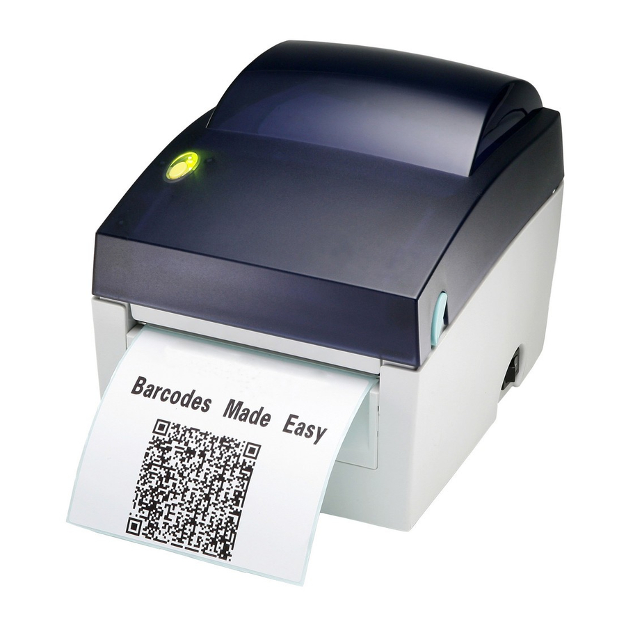
■ Barcode printer ■ Power cord ■ Switching Power ■ USB Cable ■ Label ■ Quick Start Guide ■ CD (includes label editing software QLabel / Manual) BP-DT-4 2-2. General Specifications MODEL BP-DT-4 Print Method Direct Thermal Resolution 203 dpi (8 dot/mm) - Page 5 Bitmap fonts 90°, 180°, 270° rotatable, single characters 90°, 180°, 270° rotatable Download Fonts Asian fonts 90°, 180°, 270° rotatable and 8 times expandable in horizontal and vertical directions Scalable fonts 90°, 180°, 270° rotatable 1-D Bar codes: Code 39, Code 93, Code 128 (subset A, B, C), UCC/EAN-128 K-Mart, UCC/EAN-128, UPC A / E (add on 2 &...
-
Page 6: Communication Interface
2-3. Communication Interface Serial Interface 、 、 、 、 Serial Default Setting : 9600 baud rate no parity 8 data bits 1 stop bit XON/XOFF protocol ,RTS/CTS。 RS232 HOUSING(9-pin to 9-pin) DB9 SOCKET DB9 PLUG - - - 1____________________________________1 +5V, max 500mA 2____________________________________2 3____________________________________3 4____________________________________4... -
Page 7: Printer Parts
2-4. Printer Parts LED Light FEED Key Top Cover Power Switch Cover Open Button Print Head Lift Label Rll Hlder Printer Mechanism Label Roll Core Label guide Front Cover Piece... - Page 8 Platen Cover Label Sensor Platen Roller Power Socket USB Port Fan-fold Label Insert Serial Port(RS-232) Bottom Case Cover Hang Holes...
-
Page 9: Printer Installation
3. PRINTER INSTALLATION 3-1. Label Installation 1. Place the printer on a horizontal surface and open the Top Cover 2. Press and release the lock of Label Roll Core 3. Pull up the Label Roll Holder and lift the Label Roll Core upward. - Page 10 7. Put the label under the Label Guide and stretch it frontward. 8. Pull the Label Guide inward and make it fit the edge of label 9. Close the Top Cover to complete the label installation.
-
Page 11: Label Roll Core Switch
3-2. Label Roll Core Switch 1. Pull the Label Roll Holder to the topmost and lift the Label Roll Core upward. 2. Turn the Label Roll Core outward as the figure shows. 3. Whirl the Label Roll Core back to the original position 1 Inch Core A. -
Page 12: Pc Connection
3-3. PC Connection 1. Please make sure the printer is powered off. 2. Take the power cable, plug the cable switch to the power socket, and then connect the other end of the cable to the printer power socket. 3. Connect the cable to the USB/Serial port on the printer and on the PC. 4. -
Page 13: Driver Installation
3-4. Driver Installation 1. Insert the product CD to your computer’s CD Drive and find the “Windows Drives” folder. 2. Select the icon of driver file and click it to start the installation. 3. Follow the instruction on screen to keep the installation going. - Page 14 7. Enter the printer name and set printer sharing option. 8. A description page of printer settings will be displayed after all setting are completed. 9. Check if all printer settings are correct and then press finish to start copying driver files. 10.
-
Page 15: Accessory
4. ACCESSORY 4-1. Stripper Module Installation Stripper Module Screw X 2 [Note1] Please power off the printer before installing the stripper module. [Note 2] Label liner thickness is recommended to be 0.06mm ±10% with basic weight 65g/㎡ ±6%. 1. Place the printer on a horizontal surface and open the Top Cover 2. - Page 16 5. Turn the printer around and tighten screws to fix the Stripper in location. 6. Unlock the Bottom Case Cover to see the main board of printer. [Note] You can also use coin or screwdriver to open the bottom case cover 7.
- Page 17 10. Flip the stripper downward to open it. 11. Follow the instruction on Chapter 2-1 to install the label. 12. Peel off the first label, and feed the liner through the roller and the strip bar. [Note] The label / paper used for stripper is suggested to be at least 20mm in height.
-
Page 18: Cutter Module Installation
4-2. Cutter Module Installation Cutter Module Screw X 2pcs [Note1] Please power off the printer before installing the cutter module. [Note 2] Do not cut self- adhesive labels! The traces of adhesive will pollute the rotary knife and impair safe operation! The service life of the cutter is 1,000,000 cuts for paper [Note 3]... - Page 19 3. Push the Cutter connector Into printer through the cable hole as shown in figure. 4. Place the Stripper on the fillister. 5. Turn the printer around and tighten screws to fix the Cutter in location. 6. Unlock the Bottom Case Cover to see the main board of printer.
- Page 20 10. Follow the instruction on Chapter 2-1 to install the label. [Note] It is not suggested to use label- inside paper when printing with cutter module. 11. Feed the label through the Cutter and press the FEED key to complete the installation. [Suggestion] When printing with cutter module, it is suggested to set...
-
Page 21: Printer Setting
5. PRINTER SETTING 5-1. FEED Key After pressing the FEED key, printer will feed the media (according to media type) to the specified stop position. When printing with continuous media, pressing the FEED key will feed the media out to a certain length. -
Page 22: Self-Test
5-4. Self - Test The Self-Test page helps user to figure out whether the printer is operating normally. Below are some general descriptions about the content of Self-Test page: 5-5. Dump Mode There are two ways to send printing commands to the printer. One is sending through the command window of QLabel IV, the other is sending through Windows HyperTerminal via RS-232 port. -
Page 23: Error Messages
5-6. Error Messages LED Light Beep Description Solution Wait for the print head temperature drops to the normal None Print head temperature high. temperature range, printer will go (Flash) back to the standby mode and the LED light will stop flashing. Make sure the movable sensor mark the correct position, Unable to detect paper. -
Page 24: Maintenance And Adjustment
6. MAINTENANCE AND ADJUSTMENT 6-1. Thermal Print Head Cleaning Unclear printouts may be caused by dusty print head, ribbon stain or label liner glue. Therefore when printing, it’s necessary to keep the top cover closed. Also, check and prevent paper/label from being stained or dusty to ensure print quality and to prolong the print head life. -
Page 25: Adjust The Cutter
6-2. Adjust the Cutter When using Cutter, paper-jam may happen sometimes. It can be solved by adjusting the cutter. 1. Turn the printer around to see the Cutter Cover Screw. 2. Loose the Cutter Cover Screw to remove the Cutter Cover 3. -
Page 26: Troubleshooting
6-3. Troubleshooting LED light does not light up after • Check the power connector on the printer • Check for software setting or program command errors • Replace with suitable label • Check if label may run out • Check if label is jammed/tangled up LED light indicates error •... - Page 27 MEMO...
- Page 28 MEMO...
- Page 29 MEMO...
- Page 30 뒷표지 뒷표지...
Need help?
Do you have a question about the BP-DT-4 and is the answer not in the manual?
Questions and answers