
Subscribe to Our Youtube Channel
Summary of Contents for ECKELMANN CI 3000
- Page 1 Operating instruction Store Computer CI 3000 / CI 3100 Extension module SIOX Version V5.12 Version 2.09 09. April 2014...
- Page 2 All rights to any use whatever, utilisation, further development, forwarding and creation of copies remain with the Eckelmann AG company. In particular, neither the contract partners of Eckelmann AG nor other users have the right to distribute or mar ket the IT programs/program parts or modified or edited versions without express written permission. To some extent, names of products/goods or designations are protected for the respective manufacturer (registered trademarks etc.);...
-
Page 3: Table Of Contents
............System Design of CI 3000 . - Page 4 ......Installation and Startup of CI 3000 / SIOX ....... .
- Page 5 Pin and Terminal Assignments of CI 3000 / SIOX ......CI 3000 Store computer terminal diagram .
- Page 6 ....... . . Order numbers and accessories of CI 3000 .
-
Page 7: Conventions
Conventions Explanation of 'General Instructions' A general instruction is composed of two elements: 1. A pictogram of a hand at the side of the page as well as 2. The actual text: For example: Further information on the device's degree of protection is contained in the chapter ”Technical Data”. Explanation of 'Safety Instructions and Hazard Warnings' Safety instructions or hazard warnings are composed of four elements: 1. -
Page 8: Warning Signs And Symbols Employed
Warning Signs and Symbols Employed Explanation of the warning signs and symbols employed for the safety instructions and hazard warnings in this documentation: S Attention symbol - general hazard warning 1. Hazard warning The attention symbol indicates all safety instructions in this operating instruction and service manual, which, if not observed, could result in danger to life and limb. -
Page 9: Safety Instructions
Safety instructions Safety instructions The safety regulations, codes and notes contained in this section must definitely be observed and complied with at all times. During repairs on the entire LDS system, the accident prevention regula tions and general safety instructions must be observed. Important information (safety instructions and hazard warnings) are indicated by corresponding symbols (see page 1 of the chapter ”Conven... -
Page 10: Disclaimer In The Event Of Non-Compliance
Safety instructions Work on electrical equipment may only be undertaken by authorized and duly trained personnel (as defined by DIN/VDE 0105 and IEC364) with full observance of the currently valid regulations contained in the following: - VDE Regulations - Local safety codes - Intended use see chapter 1.3 - BGV A3 - Five Safety Rules... -
Page 11: Intended Use
This control system may only be used for the purpose for which it is intended: The CI 3000 control system has been designed for use as store computer in commercial, industrial refrigeration systems and building management systems with the intended functional scope as described in these operating instructions, and it is to be used under the environmental conditions in these instructions. -
Page 12: Electrostatic Sensitive Devices (Esds)
Safety instructions 1.5 Electrostatic sensitive devices (ESDs) Electronic components and assemblies (e.g. printed circuit boards) are vulnerable to electrostatic discharge. Regulations for handling and working with electrostatic sensitive devices must definitely be observed and complied with, see also section 1.5.1! All electrostatic sensitive devices (ESDs) are identified by the warning sign illustrated. -
Page 13: System Design Of Ci 3000
The CI 3100 has a third interface (COM3), see Section 2.1. The CI 3000 Store Computer is the central unit of the LDS System.It can be operated via the integrated key board, the operator terminal of the AL 300 and/or remotely via a host system, i.e. on-site service PC with LDSWin software. -
Page 14: Circuit Points
System Design of CI 3000 2.1 Circuit points The CI 3000 Store Computer has the following connections (see also section 5 for further details of - Pin and Terminal Assignment): Interfaces CI 3000 S CAN bus port to interconnect all LDS components (e.g. case/coldroom controllers of UA 300 / UA 400 Series,... -
Page 15: New Features Compared To Previous Versions
‐ AUX relay can be used as an alarm relay ‐ Daily test alarm for inspecting the alarm route ‐ Fast CAN bus connection between CI 3000 and Combi Gateway Danger of a loss of the configuration! Due to more fundamental changes to the store computer, during an update from version < 5.0 to version 5.0 and higher it is necessary to re-enter all settings for the error message transmission. - Page 16 System Design of CI 3000 ‐ EU archiving with Data Logging Controller UA 300 L as per EU regulation (the UA 300 L records the temperatures in place of the refrigeration controller). ‐ 24-h actual values and energy archives can be reloaded (e.g. following a firmware update) ‐...
- Page 17 (limited time duration 1 to 255 min.) ‐ Alarm takeover (by service center) ‐ Store computer check initiated by CI 3000 ‐ Access control by Store ID ‐ Enabling of setpoint adjustment for specific LDSWin dongles ‐...
- Page 18 CAN bus dongle) available but not recommended S Operator Terminal AL 300 When a CI 3000 Store Computer is connected to the LDS System, the AL 300 Operator Terminals used must also be the same Version: ⇒ AL 300 CI 3000 V5.0...
-
Page 19: Application Of Ci 3000
S Centralized time synchronization (master clock): Date and time can be set with the CI 3000 Store Computer for the complete system. The CI 3000 Store Com puter also performs cyclic synchronization of internal clocks in all LDS components via the CAN bus. The CI 3000 contains a battery-backed real-time clock, which supports automatic daylight saving change. - Page 20 Application of CI 3000 Notice: Version 2.09 09. April 2014...
-
Page 21: Function Of Ci 3000
Menu 4) serves as a log of all faults that have occurred and been corrected and reported events. Reports gener ated by LDS components are transmitted to the CI 3000 Store Computer via the CAN bus with one of the follow... -
Page 22: Acknowledgement Of Alarms And Messages
- Call made to store - Manual/automatic mode of LDS components - Changed configuration or date/time Detailed information on the alarm and message texts of the CI 3000 store computer is provided in the chapter 10 - Alarms and Messages. 4.1.1 Acknowledgement of alarms and messages Alarms can be reset by pressing the ALARM RESET key while the alarm log is displayed (see Menu 1). -
Page 23: Remote Alarm Messaging
Function of CI 3000 4.1.2 Remote alarm messaging 16 alarm destinations are available for remote alarm messaging. The destinations can be: S A PC with the PC software LDSWin S An SMS recipient S FAX machine and S A telephone for the receipt of a voice message... -
Page 24: The Priority Concept
Function of CI 3000 4.1.2.1 The priority concept Possible priorities for alarms and messages have now been raised from the previous --, 0, 1 and 2 to 99. This priority range is divided into 10 alarm groups (decades 0..9): PRIOx1 PRIOx2 PRIOx ..x... - Page 25 Function of CI 3000 Procedure with example: 1. Specify the alarm destinations The refrigeration plant is to register with the service centre and the building control technology by the caretaker. 2. Specify the priorities and priority groups and assign them to the alarm destinations Refrigeration plant: Priorities 0..9...
-
Page 26: Suppressing False Alarms Caused By Maintenance Work (Service Mode)
If alarms are generated during the active service mode these are normally entered in the alarm and messages list of the CI 3000, and, if available, the AL 300 operator terminal. But the horn, buzzer and alarm relays remain deactivated and automatic fault report transmission is not initiated. In addition, no alarm messages are sent to any user PC within the installation connected by direct coupling;... -
Page 27: Relay Outputs
PRIO1 / PRIO2 alarm relay The CI 3000 Store Computer has a digital alarm output (floating relay contact) for each alarm priority X1 and X2, usable for example to operate a telephone dialer (terminals PRIO1: 35, 36, 38 / PRIO2: 25, 26, 28, see chapter 6.1.3). -
Page 28: Digital Inputs
230 V AC relay outputs are off load! The CI 3000 Store Computer has two 230 V AC digital inputs: A1, A2 and B1, B2. These can be configured for the monitoring and alarm messaging of external maintenance groups (external alarms), i.e. -
Page 29: Special Inputs
Function of CI 3000 4.3.2 Special Inputs The special digital inputs are initially deactivated and must be configured before use in menu 6-1-3. The following special inputs are available: Block lock: recognises whether the store is open or closed (used for building management control technology applications). -
Page 30: Can Bus Station Monitoring
Shutdown of an LDS component is detected by CAN station monitoring as a failure (Screen 7-1). This causes a prompt to appear on the display of the CI 3000 Store Computer and all AL 300 Operator Terminals (when used) asking whether the LDS component has been shut down intentionally. -
Page 31: Configuration Of The Lds System Via The Pc Software Ldswin
Further information is contained in the LDSWin operating instruction. For local configuration the CI 3000 Store Computer is connected to the PC by a null modem cable (EAG No. PCZKABSER2). -
Page 32: Eu Archive
4.9.1 Archive memory requirements Three versions of the CI 3000 Store Computer are available at the present time, differing by size of data mem ory (2 MB, 6 MB or 16 MB). (The CI 3100 is only available with 6 and 16 MB memory expansions) - Page 33 Function of CI 3000 Examples (assembled with all sensors): CI 3000 Store Computer with 2 MB of memory: 40 memory units Number Memory units required 16 refrigeration points UA 300 / UA 300 D/L/V or 16 x 1,4 ~23 10 refrigeration points UA 300 E / UA 400 E...
-
Page 34: Timers
Function of CI 3000 4.10 Timers When employing extension modules (SIOX ), timers with up to 7 switching times per relay output can be confi gured in menu 6-1-7. Control times can be set accurate to the minute and can be spread over individual weekdays or groups of weekdays: (Mo-Fr, Mo-Sa, etc.). -
Page 35: Totalizer And Peak Load Monitoring
Function of CI 3000 4.11.1 Totalizer and peak load monitoring With the assistance of the totalizer (see picture in the following chapter), the values of a number of metering points (e.g. meter for electricity, water, gas and heat) in menu 6-1-6-2 can be combined to generate a total value. - Page 36 Function of CI 3000 LSM is then able to recognize whether the unit is in fact working and contributing to peak demand and whether it responds to the load shedding command. For this operating mode a digital relay input and output on the SIOX extension module (SIOX 1 ..
-
Page 37: M-Bus Interface For Consumption Data Capture
Function of CI 3000 the system operator and information gathered by the LDSWin software from the plant power demand profile. Correct adjustment of setpoints, meaning efficiency and reliability of the load optimization system, can readily be reviewed and checked from this recorded data. -
Page 38: Integration Of Refrigeration Controllers
7-6. For detailed information see the operating manual ”LDS1 Gateway”. Connection to the store computer: CI 3000: connected via the COM2 interface using a RS232-RS485 converter. CI 3100: connected via the COM3 interface. For more detailed information, see ”Connecting compact case controllers” in Section 5.7. -
Page 39: Installation And Startup Of Ci 3000 / Siox
Important safety instructions! The store computer is designed exclusively for panel mounting! The CI 3000 Store Computer is assembled in a metal cage with plastic front. The power consumption of the store computer is 24 VA. For each of the additional SIOX extension modules, up to a maximum of 4, an additional 2 W of power input is required. -
Page 40: Can Bus
Installation and Startup of CI 3000 / SIOX Insert the CI 3000 Store Computer with fitted rubber gasket (2) from the outside into the cutout in the control panel (3) and fasten to the mounting frame behind (4) by four screws (6):... -
Page 41: Modem
5.3 Modem If a modem is to be used on the CI 3000 Store Computer for automatic fault report transmission and remote maintenance, the modem type must be set in Menu 6 Store Computer - 1 Configuration - 8 Modem - 1 Modem... -
Page 42: Sms Text Message Transmission Via A Gsm Modem
2. Now the time interval (30..120 min.) between 2 resets can be set in menu 6-1-8-3. The CI 3000 Store Computer now switches off the modem for short periods on a cyclical basis in accordance with the specified time interval (ca. 10 seconds):... -
Page 43: Local Configuration Lds-System By Service Pc
Simply connecting the null modem cable is not sufficient! If the CI 3000 store computer is unable to detect a modem or has not switched to the ”Direct coupling mode”, then the alarm Modem fault is generated following the elapse of a parameterisable time period (see menu 7-4). -
Page 44: Siox Extension Modules - For Din Rail Mounting
- without manual control switch - with manual control switch in order to switch the digital outputs manually (see picture) The modules are connected to the CI 3000 store computer via SIOX power supply cables, i.e. SIOX data cables (see capter 5.5.1). -
Page 45: Siox - Connecting To The Store Computer
25 Ohm/km. S Max. permitted cable length is 50 m. S The power supply of the CI 3000 store computer is designed for a maximum of 4 extension modules. SIOX data lines S The data cables (SIOX IN / SIOX OUT) should not be routed in the immediate proximity of high voltage or high frequency cables. -
Page 46: Configuring Of Siox
Low-voltage DC signals, e.g. 24 V DC, are not recognized. Exception: - 24 V DC meter pulses are detected (S0 interface, CI 3000/CI 3100 ONLY)! Condition: 1. Minus 24 V DC MUST be supplied at the terminal level (A2 .. L2)! Condition: 2. -
Page 47: Siox - Connecting To Energy, Gas And Water Meters
(conversion ratio of current transformer) Allowance must be made for the meter and transformer constant settings when using electronic me ters, as otherwise energy evaluation by the CI 3000 Store Computer will be inaccurate due to faulty meter and transformer ratios! - Page 48 Installation and Startup of CI 3000 / SIOX Connection and wiring examples for energy, gas and water meters on SIOX extension module: EXAMPLE 1: 4-WIRE PHASE POWER SYSTEM, ANY LOAD GOSSEN METRAWAT S0 IMPULS OUTPUT TYPE: U1389 CONVERTER CONNECTIONS 9 11...
-
Page 49: Calculation Of Consumption/Capacity From Meter Values
Installation and Startup of CI 3000 / SIOX 5.5.3.1 Calculation of Consumption/Capacity from Meter Values Settings on the store computer For the calculation of consumption and capacity from the meter values of energy and quantity meters the meter constant and transformer constant in the store computer must be set under menu 6-1-6-1. -
Page 50: Dc Supply Via Siox Terminals 93 And 94
24 V DC supply via SIOX terminals 93 and 94 In addition to the maximum four SIOX Extension Modules the CI 3000 Store Computer can supply 24 V DC power to other external loads. This power can be taken from terminals 93 (-) and 94 (+) on the SIOX Extension Module. -
Page 51: Special Functions For Startup
(is entered in message log). ‐ Simultaneously press the MODE and ESC and 8 keys to perform restart. Frequent restarting while the CI 3000 Store Computer is powering up (about 2 min.) can result in errors in archive management. -
Page 52: Connecting Case Controllers
Installation and Startup of CI 3000 / SIOX 5.7 Connecting case controllers S Marktrechner CI 3000 Modbus connection of compact case controllers (e.g. UA 30) i.e. case controllers of the LDS1 system via LDS1 gateway with RS232-RS485 converter at the COM2 interface:... -
Page 53: Connection Of The M Bus Gateway
Installation and Startup of CI 3000 / SIOX 5.8 Connection of the M Bus Gateway M bus meters such as energy, gas, warm water or water meters can be connected to the store computer using the M bus gateway. In order to do this the M bus gateway must be connected to the store computer’s COM2 interface using the in... -
Page 54: M-Bus-Gateway Status Leds
Installation and Startup of CI 3000 / SIOX The following transmission rates and distances are possible with the cable type J-Y(ST)Y 2x2x0.8 mm: Transmission rate No. of M-bus meters Length ≤ 10 300 Baud max. 4000 m ≤ 20 max. 3200 m ≤... -
Page 55: Dip Switch / Jumpers
Installation and Startup of CI 3000 / SIOX 5.9 DIP Switch / Jumpers Neue model: Standard settings for the DIP switches The DIP switches are positioned on the top left hand side of the store computer's housing: Danger of failure of alarm messaging! During normal operation the DIP switch WDOG (Watchdog) must be set to ON and the DIP switch BOOT set to OFF! Otherwise the watchdog mon... -
Page 56: Firmware Update
5.10 Firmware update New firmware is loaded to the CI 3000 Store Computer by running the Update CI3000 Vx.xx.exe program on a PC connected to the MODEM port of the CI 3000 Store Computer by null modem cable (EAG No. PCZKABSER2). -
Page 57: Downloading Software Update
Danger of a loss of the configuration! All archives and configurations will be lost when updating the software! In order to safeguard the configuration of the CI 3000 Store Computer a complete ar chiving using the PC software LDSWin must be carried out before a firmware update. Following up... - Page 58 S Double click the update software CI3000_Vx.xx.exe to run the program. S Click OK to start download and follow the instructions on the screen, e.g. restart the CI 3000. S Turn off power to the CI 3000 Store Computer when download is completed.
-
Page 59: Replacing The Battery
Installation and Startup of CI 3000 / SIOX 5.11 Replacing the battery Battery replacement is only possible with models supplied after 01 January 2009. The Store Computer contains a backup battery (type: 1,2 Ah / 1/2 AA / 3,6 V Lithium). A Battery Low alarm (Er... - Page 60 Installation and Startup of CI 3000 / SIOX Carefully turn the Store Computer over face up, lift the front panel and disconnect the green two-pin con nector (see arrow in the picture) from the small switch wiring board. Leave the other connectors in place!
- Page 61 Installation and Startup of CI 3000 / SIOX Now unbolt the battery holder carefully on the right and left, gently levering it out with a screwdriver and then lifting it upwards: Then pull the battery from the battery holder and dispose of it in a proper manner.
- Page 62 Installation and Startup of CI 3000 / SIOX Notice: Version 2.09 09. April 2014...
-
Page 63: Pin And Terminal Assignments Of Ci 3000 / Siox
Pin and Terminal Assignments of CI 3000 / SIOX Pin and Terminal Assignments of CI 3000 / SIOX 6.1 CI 3000 Store computer terminal diagram (CI 3100 ONLY) COM 3 COM 2 MODEM 9-PIN 9-PIN 9-PIN D-SUB CONNECTOR D-SUB CONNECTOR... -
Page 64: Terminal Assignment For 230 V Ac Power Supply
Pin and Terminal Assignments of CI 3000 / SIOX 6.1.1 Terminal assignment for 230 V AC power supply The connection provides the store computer with power and is located on the underside of the device. Warning - hazardous electrical voltage! -
Page 65: Terminal Assignment For 230 V Ac Relay Outputs
Pin and Terminal Assignments of CI 3000 / SIOX 6.1.3 Terminal assignment for 230 V AC relay outputs The two relay outputs PRIO1/PRIO2 can be used for sending alarm messages. The multifunctional output AUX can be freely configured (see table). The terminals are located on the underside of the device. -
Page 66: Terminal Assignment For Can Bus
Pin and Terminal Assignments of CI 3000 / SIOX 6.1.4 Terminal assignment for CAN bus The terminals for connecting the store computer to the CAN bus are located on the underside of the device. Warning - hazardous electrical voltage! If mains voltage is connected to the CAN bus terminals,... -
Page 67: Siox - Extension Module Terminal Diagram
Pin and Terminal Assignments of CI 3000 / SIOX 6.2 SIOX - Extension module terminal diagram Warning - hazardous electrical voltage! In order to guarantee reverse voltage protection, only coded mating plugs are to be used on the assembly connections. -
Page 68: Siox - Terminal Assignment Of Digital Inputs 24 V Ac/Dc / 230 V Ac
Pin and Terminal Assignments of CI 3000 / SIOX 6.2.1 SIOX - Terminal assignment of digital inputs 24 V AC/DC / 230 V AC The 12 digital inputs (24 V AC / 230 V AC) are designed for installation monitoring and as meter inputs. -
Page 69: Siox - Terminal Assignment For 230 V Ac Relay Outputs
Pin and Terminal Assignments of CI 3000 / SIOX 6.2.2 SIOX - Terminal assignment for 230 V AC relay outputs For week timers (e.g. for defrosting, lighting, car park lighting) or for energy management (e.g. load shedding or the enabling of consumers). -
Page 70: Siox - Terminal Assignment Of The Interfaces
In the event of an Ethernet network cable with PoE (Power over Ethernet) being used instead of the SIOX data cable (RJ45) damage can occur to participating network devices! Only components approved by Eckelmann AG may be connected to the SIOX extension bus (termi nals SIOX OUT/SIOX IN i.e. terminals 91..95). -
Page 71: Operation Of Ci 3000
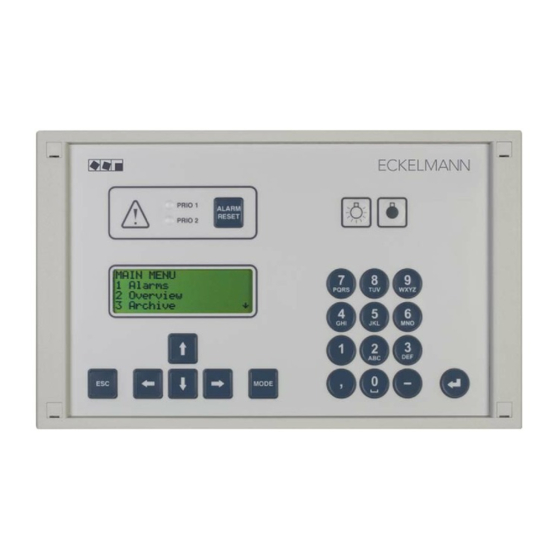
Operation of CI 3000 Operation of CI 3000 7.1 Operating interface (11) PRIO 1 ALARM RESET PRIO 2 PQRS WXYZ MODE (10) Priority 1 alarm indicator light Priority 2 alarm indicator light Reset key to stop buzzer and horn (AUX) and cancel alarms... - Page 72 (→). The letters show their order in the screen. Menu CI 3000 / CI 300 / AL 300 Screens CI 3000 / CI 300 / AL 300...
- Page 73 Operation of CI 3000 Scrolling Use the cursor keys ( ↑ ) and ( ↓ ) to: ‐ Scroll line by line, for example when selecting a variable in a line from a list of predefined variables. ‐ Scroll block by block to view values that extend beyond the capacity of the display.
-
Page 74: Deactivate Entry Block
Operation of CI 3000 Exiting menus and screens Press the ESC key to exit the menu or screen you are in at any time. This returns you to the next higher menu. All menus and screens are closed automatically if no key is pressed for 10 minutes. The display then jumps to the Main Menu or to the Alarm menu if any fault report is currently active. -
Page 75: Superuser Mode (Granting Superuser Rights)
Operation of CI 3000 7.2.2 Superuser mode (granting Superuser rights) Superuser mode is reserved exclusively for use by service personnel! With activated setpoint interlock (restricted setpoint changes) a password is necessary. For detailed instructions see menu 9-3. Before any values can be entered, the entry block must be deactivated as follows: ‐... -
Page 76: Remote Operation/Parameter Setting Of A Lds Component
Operation of CI 3000 7.3 Remote operation/parameter setting of a LDS component The LC display contains 4 lines of 20 characters. If a menu or screen contains more than 4 lines, the cursor keys can be used to scroll through the remaining lines. -
Page 77: Menu Structure Of Ci 3000
Menu structure of CI 3000 Menu structure of CI 3000 8.1 Main menu Level 1 Level 2 Level 3 Screen No. Screen Name Main menu MAIN MENU 1 Alarms ALARM XXX 2 Overview OVERVIEW 3 Archive ARCHIVE 4 Messages MSG/ALARM... - Page 78 Menu structure of CI 3000 8 I/O Monitor I/O MONITOR Digital I/O 8-1 * DIGITAL I/O Analog I/O 8-2 * ANALOG I/O SysInfo SYSINFO Post Mortem 8-4 * CAN Test 8-5 * CAN TEST Modbus Status MODBUS Serial Test 8-7 *...
-
Page 79: Menu Main Menu
Alarms remain listed in the log until they are reported as corrected and reset by the user. If an LDS component reports an alarm while the CI 3000 Store Computer main menu is displayed, the menu changes automatically to show the alarm log and the most recent alarm received. -
Page 80: Menu 2 General Overview
Menu structure of CI 3000 S Screen 1-a Entry Display Page 2 - Alarm still active ↑ ↓ ← Heading with Node No. of alarm-generating component ALARM XXX Nd.nnn Name of alarm-generating component Node Name ON ← Time of alarm occurrence dd.mm.jj... -
Page 81: Menu 4 Message Log (Event Log)
Menu structure of CI 3000 S Screen 3-a Shows archived data ARCHIVE Pos: XXXXX Date, time ARCHIVE Pos. XXXXX Mi 19.12.05 12:06 Zone 1: Temperature zone 1 Zone 1: OCDGA ttt°C - O, C, D, G, A: - Abbreviation for different operating conditions of the refriger point ttt°C: - Display tempera... -
Page 82: Menu 5 Remote Control
Terminal mode will be closed automatically if no key is pressed for 10 minutes and the main menu or alarm log of the CI 3000 Store Computer will be displayed. Any entry made at the time by the user but not yet confirmed will be cancelled. - Page 83 Menu structure of CI 3000 S Screen 6-1 Configuration The separate configuration menus can be selected from this list by the number 1 to 8. Use the up and down cursor keys (↑) (↓) to navigate through the list. CONFIGURATION...
- Page 84 S Screen 6-1-1 Expansion Stage When SIOX Extension Modules are connected to the CI 3000 Store Computer, the number of connected mod ules must be configured in this screen. If this is not done, the modules will not be recognised and supported by the CI 3000 Store Computer.
- Page 85 No: ESC Designations of modules/channels supported by the CI 3000 Store Computer for digital inputs: Int.I Internal input AL1 (terminal A1, A2) or AL2 (terminal B1, B2) of CI 3000 Store Computer. SIOX1 1st Extension Module, channel 1 to 12...
- Page 86 If activated, the input can be deactivated under the DELETE menu item (parameters are reset to default set ting). If the input has generated an alarm at the time, the alarm will be reported as sent. Designations of modules/channels supported by the CI 3000 Store Computer for the digital input: SIOX1...
- Page 87 Menu structure of CI 3000 S Screen 6-1-4 Alerting The CI 3000 store computer distinguishes between 100 alarm priorities (0..99) Furthermore it supports 16 alarm destinations (see chapter 4.1). ALERTING Configuration of the alarm relay, i.e. multifunctional output (AUX) 1 Alarm Relay...
- Page 88 Menu structure of CI 3000 S Screen 6-1-4-2 Phone Number This screen is used to enter the telephone number for fault report transmission by the keypad and special char acters ( 0123456789N*#!&:;.= ) by the cursor keys (↑) (↓). Entry...
- Page 89 0172-22 78 020 Anny Way: 0900-32 66 90 02 When using the Voice message fault report destination, the CI 3000 Store Computer calls a tone- dial telephone and plays a prerecorded voice message that has previously been saved to the CI 3000 Store Computer with the LDSWin software.
- Page 90 - during during the time period When using the Voice message fault report destination, the CI 3000 Store Computer calls a tone- dial telephone and plays a prerecorded voice message that has previously been saved to the CI 3000 Store Computer with the LDSWin software. The party receiving the call MUST acknowledge receipt of the voice message by pressing the 5 key.
- Page 91 Menu structure of CI 3000 S Screen 6-1-5 EU Archive This screen is used to select the refrigeration points (UA 300 Series) that are to be archived in accordance with ↑ ↓ the EU Directive. Use the up and down cursor keys ( ) to select the refrigeration points and press the EN...
- Page 92 Menu structure of CI 3000 Page 2 – Configure measuring location Press the ENTER key to configure the measuring location. Entry Default MEASURING POINT ↑, ↓ Select meter type: Power, water, gas Power Type Power Enter freely editable name (max. 19 characters)
- Page 93 Energy, gas and water meters). Allowance must be made for the meter and transformer constant settings when using electronic me ters, as otherwise energy evaluation by the CI 3000 Store Computer will be inaccurate due to faulty meter and transformer ratios! S Maske 6-1-6-1-2 Search M-bus Info screen for displaying existing M-bus nodes.
- Page 94 Menu structure of CI 3000 S Screen 6-1-6-2 Totalizer ↓ Use the up and down cursor keys (↑) ( ) to scroll through the separate totalizers. button, scroll to page 2, with ← button, back. → Page 1: Select totalizer, current display - page 1, with Press ENTER to configure the totalizer.
- Page 95 Menu structure of CI 3000 Page 3: Configuration totalizer Press ENTER to configure the totalizer. Entry Default SUMMING UNIT ↑ ↓ number Name and select totalizer (max. 19 characters) Name of totalizer A name should always be entered for the totalizer! ↑...
- Page 96 Menu structure of CI 3000 S Screen 6-1-6-2-a Measuring Locations MEASURING POINTS Select measuring location associated with totalizer by ENTER (↵) key Name of measuring location Only measuring locations that have been appropriately configured in Screen 6-1-6-1 as a measuring...
- Page 97 Menu structure of CI 3000 S Screen 6-1-6-3-2 LRM Levels ↓ Use the up and down cursor keys (↑) ( ) to scroll through the separate load shedding stages. Press ENTER to configure the load shedding stage selected. Page 1 - Configure load shedding stage...
- Page 98 Menu structure of CI 3000 S Screen 6-1-6-3-2-a Priority Entry Default PRIORITY √ ↑, ↓,↵, ESC √ Assign priority (1 to 20) to load shedding stage: Prio 1: First load shed ..Prio 20: Last load shed S Screen 6-1-7 Timer Each timer channel works as an independent week timer with up to 7 control times and can be assigned to a switching output and/or a pulse output.
- Page 99 Menu structure of CI 3000 Entering control times ↓ Use the up and down (↑) ( ) cursor keys to select the weekday or combination of weekdays. Press the ENTER key to apply the entry and enter the hour of the start time. Press the ENTER key again to enter the minutes of the start time and the hour and minutes of the end time.
- Page 100 S Screen 6-1-8-1 Modem Type This screen is used to specify whether a modem is connected to the CI 3000 Store Computer and the dial type to be used. As supplied, the configuration is Tone Dial. With this configuration, communication with the LDSWin software can only be made via null modem cable.
- Page 101 Menu structure of CI 3000 S Screen 6-1-8-3 Modem HW-Reset (Hardware reset) Unreliable modems can be restarted periodically (hardware reset) by switching off the power supply. In order to do this, the zero potential contact AUX (terminals 15/16/18) is configured/deployed as an interrupt switch for the modem power supply (see chapter 5.3.3 Modem Hardware-Reset).
- Page 102 Menu structure of CI 3000 S Screen 6-2 Meter Readings ↓ Use the up and down cursor keys (↑) ( ) to scroll chronologically through the archived data. Use the right cursor → key ( ) to move between pages.
- Page 103 As all of the components in the system first have to register with the store computer, no data is available in the first few minutes following the start of the CI 3000 (first start or restart)! If during this time a submenu is selected, then the message ”Function currently not available! WAIT”...
- Page 104 Menu structure of CI 3000 Page 2 - HACCP temperature archive (hourly averages) of the selected controller (i.e. case) TEMP-ARCHIV KN.nnn ↑ Position and case number of the LDS component P: XXXXX M: aaa ← Date and time period (4 hours) of the temperature values dd.mm.yy 00-03 h...
- Page 105 Menu structure of CI 3000 S Screens 6-3-2 to 6-3-4 temperature archive The temperature archives from UA 30/Dixell controllers, AHT controllers and Danfloss controllers can be selected via the 3 screens 6-3-2 to 6-3-4. As the case selection and the associated display of the temperature archive is identical for all these controllers, the instructions are provided using the example of the ”UA30/Dixell”...
-
Page 106: Menu 7 Monitoring
Detailed status of all LDS components 2 Status Configure name and item ID of all LDS components 3 Configuration Configure CI 3000 Store Computer system alarms 4 System Alarms Status of the compact controller connected via COM2 5 Status UA30/DIX Configuration of the compact controller connected via COM2 6 Config.UA30/DIX... - Page 107 Menu structure of CI 3000 The bottom line shows the current operating status of the selected LDS component. If the component is work ing, detailed information on its status is given: A minimum of one fault still exists. ALARM Operating archive has been created.
- Page 108 Menu structure of CI 3000 S Screen 7-4 System Alarms ↓ Use the up and down cursor keys (↑) ( ) to select the alarm or group of alarms. Parameters can be changed after pressing the ENTER key. Entry Default...
- Page 109 Menu structure of CI 3000 S Screen 7-5 Status UA30/Dixell This menu contains display screen reserved for use by service personnel. This screen will only be shown when - UA30/Dixel is selected in Screen 6-1-9 and - the compact controller, i.e. the case controller integrated via LDS1 Gateway is connected to the...
- Page 110 Menu structure of CI 3000 S Screen 7-7 Status AHT This menu contains display screens reserved for use by service personnel. Entry Default STATUS AHT → → Continue to Screen 7-7-a Status ↑, ↓, (0..99) Delay in minutes Delay S Screen 7-7-a This screen will only be displayed when AHT is selected in Screen 6-1-9 and an AHT gateway is connected.
-
Page 111: Menu 8 I/O Monitor
Menu structure of CI 3000 8.1.9 Menu 8 I/O Monitor This menu contains display screens reserved for use by service personnel. No further details are given for these screens except System Info, Modbus Status and Modem Status. S Screen 8-3 SysInfo Heading with Node No. - Page 112 Menu structure of CI 3000 S Screen 8-8 Modem State MODEM STATE Modem state X XXXXXX XXXXXXXXXXX X XX XX XX XXX X Modem - Status: DIRECT Configured for direct connection by null modem cable (DIRECT) Temporary direct connection by null modem cable with configured modem...
-
Page 113: Menu 9 Parameters
Menu structure of CI 3000 8.1.10 Menu 9 Parameters Entry screen to access submenus for date/time, user language and cancelling entry block for LDS components. PARAMETERS Configure date and time 1 Date/Time Select user language in complete LDS System 2 Language... - Page 114 (6 to 7 characters) must be requested from the manufacturer in conjunction with the specifica tion of the CI 3000 serial number (see menu 7-2 or the rating plate). It only authorises access for the current and following day. Afterwards, a new password must be requested! After entering the pass...
- Page 115 (6 to 7 characters) must be requested from the manufacturer in conjunction with the specification of the CI 3000 serial number (see menu 7-2 or the rating plate). It only authorises ac cess for the current and following day. Afterwards, a new password must be requested! After enter...
- Page 116 (6 to 7 characters) must be requested from the manufacturer in conjunction with the specifica tion of the CI 3000 serial number (see menu 7-2 or the rating plate). It only authorises access for the current and following day. Afterwards, a new password must be requested! After entering the pass...
-
Page 117: Menü 0 Hvac Overview
Menu structure of CI 3000 8.1.11 Menü 0 HVAC Overview Screen showing overview of store HVAC data. Screen will only be shown when DDC (digital direct control) is connected to the LDS System. HVAC OVERVIEW Outside temperature Außentemp. xx.x°C Salesroom (VR=SR=sales room) temperature setpoint Soll Raumt.VR... - Page 118 Menu structure of CI 3000 Notice: Version 2.09 09. April 2014...
-
Page 119: Decommissioning And Disposal
The scope of our delivery is designated as a component exclusively for further processing. As a consequence of this fact, Eckelmann AG does not undertake any measures for the taking back or munici pal recycling of this product as it is not supplied directly to the free market. - Page 120 Decommissioning and disposal Notice: Version 2.09 09. April 2014...
-
Page 121: Alarms And Messages Of Ci 3000
Alarms and Messages of CI 3000 10 Alarms and Messages of CI 3000 Messages Cause Correction Hardware faults 0 int. error 01 0000 CPU hardware problem With repeated occurrence replace the device int. error 02 0000 CPU or ROM hardware problem... - Page 122 Alarms and Messages of CI 3000 Messages Cause Correction Hardware faults 8 RTC Fault xxx Real-time clock of component xxx defect. Please contact Service Organization - Replace device RTC Fault Mxx Check device Mxx 9 SIOX X Fault A SIOX extension module (X =1 ...4) has failed Please contact Service Organization or a cable (terminals 91 - 95, i.e.
- Page 123 Alarms and Messages of CI 3000 Messages Cause Correction Monitoring 52 Controll.Fail. xxx No response by LDS-component to Store Com Check power supply and LDS com puter requests. ponent connection to CAN bus, i.e. Modbus. Controll.Fail. Mxx 53 Failure AHT xxx No response by AHT component.
- Page 124 LDSWin Extern 1 LDSWin Extern 2 87 Direct link Modem link temporarily replaced by direct con nection between LDSWin PC and CI 3000 Store computer (e.g. for local configuring of LDS System by service technician). Alarm- and special inputs 90 xxxxxxxxxxxxxxxxx...
- Page 125 Alarms and Messages of CI 3000 Messages Cause Correction Error messages of Modbus components 124 Coldroom door Mxx Coldroom door of component Mxx open Close door, check door switch or connecting cable 125 Defrost Fault Mxx Defrost fault of an AHT case with...
- Page 126 Alarms and Messages of CI 3000 Notice: Version 2.09 09. April 2014...
-
Page 127: Specifications Of Ci 3000 / Siox
11 Specifications of CI 3000 / SIOX For safety reasons and to guarantee important functions (e.g. alarm forwarding to a service centre via modem) only accessories approved by Eckelmann are to be used with the store computer. 11.1 Electrical data... - Page 128 Specifications of CI 3000 / SIOX Warning - hazardous electrical voltage! Danger of electric shock! BEFORE and AFTER connection it must checked that the 230 V AC relay outputs are off load! Low voltage and safety extra-low voltage must not be applied together at the relay outputs 15/16/18, 25/26/28 and 35/36/38.
- Page 129 Specifications of CI 3000 / SIOX CI 3000 Store Computer SIOX Extension Module Atmospheric pressure Transport: 660 hPa .. 1060 hPa Operation 860 hPa .. 1060 hPa Weight CI 3000 2 MB: approx. 1350 g With/without manual control switch CI 3000 6 MB: approx.
-
Page 130: Mechanical Data
Specifications of CI 3000 / SIOX 11.2 Mechanical data 11.2.1 Dimensions of the CI 3000 PRIO 1 ALARM RESET PRIO 2 PQRS WXYZ MODE (1): Control panel (2): Panel cutout Version 2.09 09. April 2014... -
Page 131: Mounting Frame For Panel Mounting
Specifications of CI 3000 / SIOX 11.2.2 Mounting frame for panel mounting (1): Mounting frame (2): Insert nut M3 Version 2.09 09. April 2014... -
Page 132: Mechanical Data, Siox Extension Module
Specifications of CI 3000 / SIOX 11.3 Mechanical data, SIOX Extension Module Without manual control switches Mating plug with cable 24 V SIOX SUPPLY OUTPUTS OUTPUTS 230 V / 24 V - INPUTS SIOX IN SIOX Extension Module without switches NR. -
Page 133: Order Numbers And Accessories Of Ci 3000
Order numbers and accessories of CI 3000 12 Order numbers and accessories of CI 3000 12.1 Store Computer Type Description Order number CI 3000 Store Computer (2 MB) LICI300051 Store Computer (6 MB) LICI300053 Store Computer (16 MB) LICI300054 CI 3100... - Page 134 Order numbers and accessories of CI 3000 Component Description Order number Package for the inte gration of AHT cases - AHT cases with Danfoss SLV controller KGLAHTAD01 - AHT cases with Wurm controller KGLAHTAD02 - AHT cases with Danfoss SLV and Wurm controller...
Need help?
Do you have a question about the CI 3000 and is the answer not in the manual?
Questions and answers