Table of Contents
Advertisement
Quick Links
Advertisement
Table of Contents

Summary of Contents for Neousys Technology PCIe-PoE334LP
- Page 1 Neousys Technology Inc. PCIe-PoE334LP User Manual Revision 1.0...
-
Page 2: Table Of Contents
ESD Precautions ........................7 About This Manual ......................... 8 Introduction PCIe-PoE334LP Specification .................. 10 Dimension ......................... 11 Setting Up Your PCIe-PoE334LP Card Unpacking Your PCIe-PoE334LP ................12 Superior View ......................12 Status LEDs ......................13 DIP Switches ......................14 2.4.1... -
Page 3: Legal Information
Legal Information Legal Information All Neousys Technology Inc. products shall be subject to the latest Standard Warranty Policy. Neousys Technology Inc. may modify, update or upgrade the software, firmware or any accompanying user documentation without prior notice. Neousys Technology Inc. will provide access to these new software, firmware or documentation releases from download sections of our website or through our service partners. -
Page 4: Contact Information
Neousys Technology Inc. (Taipei, Taiwan) 15F, No.868-3, Zhongzheng Rd., Zhonghe Dist., New Taipei City, 23586, Taiwan Tel: +886-2-2223-6182 Fax: +886-2-2223-6183 Email, Website Americas Neousys Technology America Inc. 3384 Commercial Avenue, Northbrook, IL 60062, USA (Illinois, USA) Tel: +1-847-656-3298 Email, Website China Neousys Technology (China) Ltd. -
Page 5: Notices
Disclaimer to change without prior notice. It does not represent commitment from Neousys Technology Inc. Neousys Technology Inc. shall not be liable for any direct, indirect, special, incidental, or consequential damages arising from the use of the product or documentation, nor for any infringement on third party rights. -
Page 6: Safety Precautions
Safety Precautions Safety Precautions Read these instructions carefully before you install, operate, or transport the system. Install the system or DIN rail associated with, at a sturdy location Install the power socket outlet near the system where it is easily accessible ... -
Page 7: Service And Maintenance
Service and Maintenance Service and Maintenance ONLY qualified personnel should service the system Shutdown the system, disconnect the power cord and all other connections before servicing the system When replacing/ installing additional components (expansion card, memory module, etc.), insert them as gently as possible while assuring proper connector engagement ESD Precautions ... -
Page 8: About This Manual
About This Manual About This Manual This manual introduces and describes how to setup/ install Neousys Technology PCIe-PoE334LP. As one of the first industrial low profile Power over Ethernet expansion cards on the market, it offers expandability, stability, flexibility and fast Ethernet access to peripheral devices. -
Page 9: Introduction
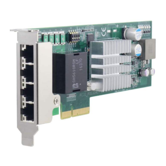
PCIe-PoE334LP Introduction PCIe-PoE334LP is the latest member of Neousys’ well-acclaimed PoE NIC card family. It is the worlds’ first low-profile form factor PoE card to integrate 4-port, server-grade GigE controller and 802.3at PoE+. The low-profile form-factor makes PCIe-PoE334LP an ideal solution with commercial off-the-shelf 2U server systems. -
Page 10: Pcie-Poe334Lp Specification
PCIe-PoE334LP PCIe-PoE334LP Specification Bus interface 4-lanes, Gen2 PCI Express interface 4x GigE ports by Intel® I350-AM4 controller, supporting 9.5 kB jumbo frame, Gigabit Ethernet Port teaming and IEEE 1588 In compliant with IEEE 802.3at-2009 (PoE+), each port delivers up to 25.5 W... -
Page 11: Dimension
PCIe-PoE334LP Dimension NOTE All measurements are in millimeters (mm). -
Page 12: Setting Up Your Pcie-Poe334Lp Card
Setting Up Your PCIe-PoE334LP Card Unpacking Your PCIe-PoE334LP Upon receiving the PCIe-PoE334LP package, please check immediately if the package contains all the items listed in the following table. If any item is missing or damaged, please contact your local dealer or Neousys Technology. -
Page 13: Status Leds
PCIe-PoE334LP Status LEDs Speed LED (1) LED Color Status Description Orange 1000 Mbps Green or Green 100 Mbps Orange 10 Mbps Active/Link LED (2) LED Color Status Description Ethernet port is disconnected Yellow Ethernet port is connected and no data transmission... -
Page 14: Dip Switches
PCIe-PoE334LP DIP Switches PCIe-PoE334LP features individual per-port power on/off control via Neousys’ API so you may manually cut off or resume the power delivery to the connected PoE device. This feature is designed for failure recovery in the field to reset connected devices. In case you have installed multiple cards, there is a set of DIP switches (indicated in blue) for users to configure board ID. -
Page 15: Board Id Settings
PCIe-PoE334LP 2.4.2 Board ID Settings The following illustrations describe DIP switch board ID settings. When installing multiple cards, please remember to set a different ID for each card. Board ID DIP Switch Position (P1 ~ P3) -
Page 16: Pcie-Poe334Lp Card Installation
PCIe-PoE334LP PCIe-PoE334LP Card Installation Once you have set up the DIP switch ID of your PCIe-PoE334LP for multi-card installation, then you are ready to install the PCIe-PoE334LP into the system. To install the PCIe-PoE334LP, please refer to the following procedure. -
Page 17: Hardware Installation
Power off and unplug the power cable from the system you wish to install to. Open the chassis (side panel) of the computer you wish to install the PCIe-PoE334LP into. Locate the x4 PCIe slot or a spare and compatible x16/ x8 PCIe slot. - Page 18 PCIe-PoE334LP Secure the PCIe-PoE334LP to the chassis with a screw. Reinstall the system’s chassis (panel) to complete the hardware installation process.
-
Page 19: Software Installation
If your system does not have a DVD-ROM, please go here to download the latest driver for PCIe-PoE334LP. Simply follow instructions to complete the software installation process. You may begin using your PCIe-PoE334LP after hardware/ software components have been installed. -
Page 20: Driver And Network Settings
PCIe-PoE334LP Driver and Network Settings PCIe-PoE334LP offers Gigabit Ethernet connectivity via Intel® I350-AM4 GbE controller. When connecting to a high-speed PoE device, such as a GigE camera, you can configure driver settings for optimum transmission throughput and connection stability. Jumbo Frame Jumbo frames are Ethernet frames with more than 1500 bytes of payload. - Page 21 PCIe-PoE334LP Right click on the corresponding Local Area Connection (Intel I350 Gigabit Network …) and select Properties.
- Page 22 PCIe-PoE334LP Click on the Configure button, the following dialog appears and click on the Advanced tab.
- Page 23 PCIe-PoE334LP Highlight Jumbo Packet and select a jumbo frame size from the Value drop-down list (9014 Byte is recommended for connecting devices with high data rate).
-
Page 24: Receive Buffers
PCIe-PoE334LP Receive Buffers Receive Buffers is another option which can affect data throughput. It determines the size of memory buffer allocated for receiving data. Increasing the size of Receive Buffers can improve the performance of receiving data. The default setting of Receive Buffers is 256 bytes. When connecting to an Ethernet device that generates large amount of data, you can set this option to a larger value (maximum 2048 bytes) for better performance. - Page 25 PCIe-PoE334LP Right click on the corresponding Local Area Connection (Intel I350 Gigabit Network) and select “Properties”.
- Page 26 PCIe-PoE334LP Click on the Configure button, the following dialog appears and click on the Advanced tab.
- Page 27 PCIe-PoE334LP Highlight Performance Options and click on Properties.
- Page 28 PCIe-PoE334LP Highlight Receive Buffers and enter a setting into the Value column (2048 Bytes is recommended for connecting devices with high data rate).
-
Page 29: Transmit Buffers
PCIe-PoE334LP Transmit Buffers Like Receive Buffers, Transmit Buffers can affect the transmission performance. The default setting of Transmit Buffers is 512 bytes. If you encounter a performance issue while transmitting data, you can adjust the size of Transmit Buffers to a larger value (maximum 2048 bytes) for better performance. - Page 30 PCIe-PoE334LP Right click on the corresponding Local Area Connection (Intel I350 Gigabit Network) and select Properties.
- Page 31 PCIe-PoE334LP Click Configure button, the following dialog appears and click on the Advanced tab.
- Page 32 PCIe-PoE334LP Highlight Performance Options and click on Properties.
- Page 33 PCIe-PoE334LP Highlight Transmit Buffers and enter a setting into the Value column (2048 Bytes is recommended for connecting devices with high data rate).
-
Page 34: Appendix A Using Per-Port Poe On/Off Control
Appendix A Using Per-Port PoE On/Off Control PCIe-PoE334LP supports power on/off control for each of its PoE ports. With provided function APIs, users can turn on or turn off the power of each PoE port manually for fault-recovery or device power reset purpose. To use the function, you need to install the WDT_DIO_Setup.exe driver package. - Page 35 PCIe-PoE334LP 2. Click “Next >” and you may specify a directory you would like to install the files to or you can install to the default directory “C:\Neousys\WDT_DIO”.
- Page 36 PCIe-PoE334LP 3. Once the installation is finished, a dialog appears to prompt you to reboot the system. The WDT & DIO library will take effect after the system rebooted. 4. When you programming your program, the related files are located in...
-
Page 37: Per-Port On/Off Control Function Reference
PCIe-PoE334LP Per-Port On/Off Control Function Reference PCI_GetStatusPoEPort Syntax BYTE PCI_GetStatusPoEPort(DWORD boardId, DWORD port); Description Acquire current power on/off status of designated PoE port. boardId DWORD value (0 ~ 7) to indicate board ID set for your card. Please refer to DIP switch settings for your PCIe-PoE card. -
Page 38: Pci_Enablepoeport
PCIe-PoE334LP PCI_EnablePoEPort Syntax BOOL PCI_EnablePoEPort(DWORD boardId, DWORD port); Description Enable (turn on) PoE power for designated PoE port. boardId DWORD value (0 ~ 7) to indicate board ID set for your card. Parameter Please refer to DIP switch settings for your PCIe-PoE card. -
Page 39: Pci_Disablepoeport
PCIe-PoE334LP PCI_DisablePoEPort BOOL PCI_DisablePoEPort(DWORD boardId, DWORD port); Syntax Description Disable (turn off) PoE power for designated PoE port. boardId DWORD value (0 ~ 7) to indicate board ID set for your card. Parameter Please refer to DIP switch settings for your PCIe-PoE card.
Need help?
Do you have a question about the PCIe-PoE334LP and is the answer not in the manual?
Questions and answers